INSTRUCTIONS
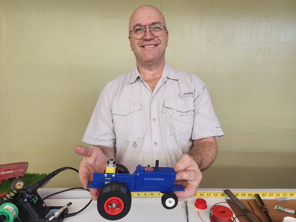
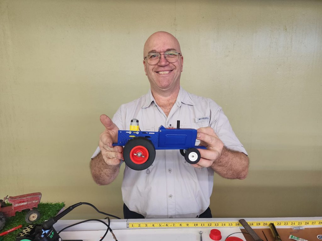
Thanks for purchasing a Mech Tech Models pulling tractor. This model can deliver a lifetime of fun. You will be amazed at its ability to respond and perform just like the full-sized counterparts. Coupled with the Mech Tech Models automatic sled, you can get together with family, friends, and neighbors for full throttle fun!
These models are clean and maintenance free. The pulling track can be any smooth surface on a couple of tables set end to end. Tile floors work well also. It is best to finish bare wood surfaces with flat or matte paint. The slick tires on these tractors grip gloss paint too well and you will not get the realistic wheel slippage, particularly at the end of the pull. We found out during testing that the pink Styrofoam board available at building centers works very well, plus it is light, can be handled, and stored easily. A half inch sheet cut in half the long way will give you a 2-foot wide, 16-foot-long track if you have the space.
The tractors are powered by a 9-volt battery and a 90-degree gearmotor. RPMs can be different but between 110 and 200 RPM. You will also have the option to change gears easily, Kits are supplied with two pinion gears and 3 planetary gears, for 6 different speeds. You will have the option to “soup” your tractor up to 18 volts supply from standard 9 volts. This will double the RPM output of the motor.
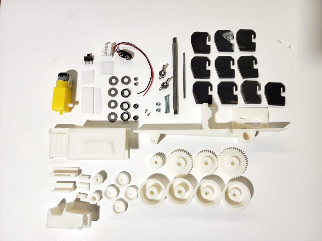
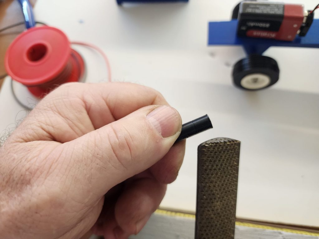
When you open the package, please check the contents with the parts list to be sure everything is there. The printed plastic parts are packaged just as they come off our printers. There are a few areas on some of the parts that will have “support material” attached. It is easy to remove using needle nose pliers, a small screwdriver and an Exacto blade. A small file can put the finishing touches to some of the edges, and a drill bit can finish the holes if needed. All these tools are offered on our website, (mechtechmodels.com) if needed.
There will also be some soldering to be done on the motor terminals and the main switch. All the other connections are made in the terminal block you will glue to the front side of the dash panel under the hood or body.
Please below for step-by-step instructions. We also suggest watching our instructional videos on mechtechmodels.com
Step 1
Step 1
Step 2
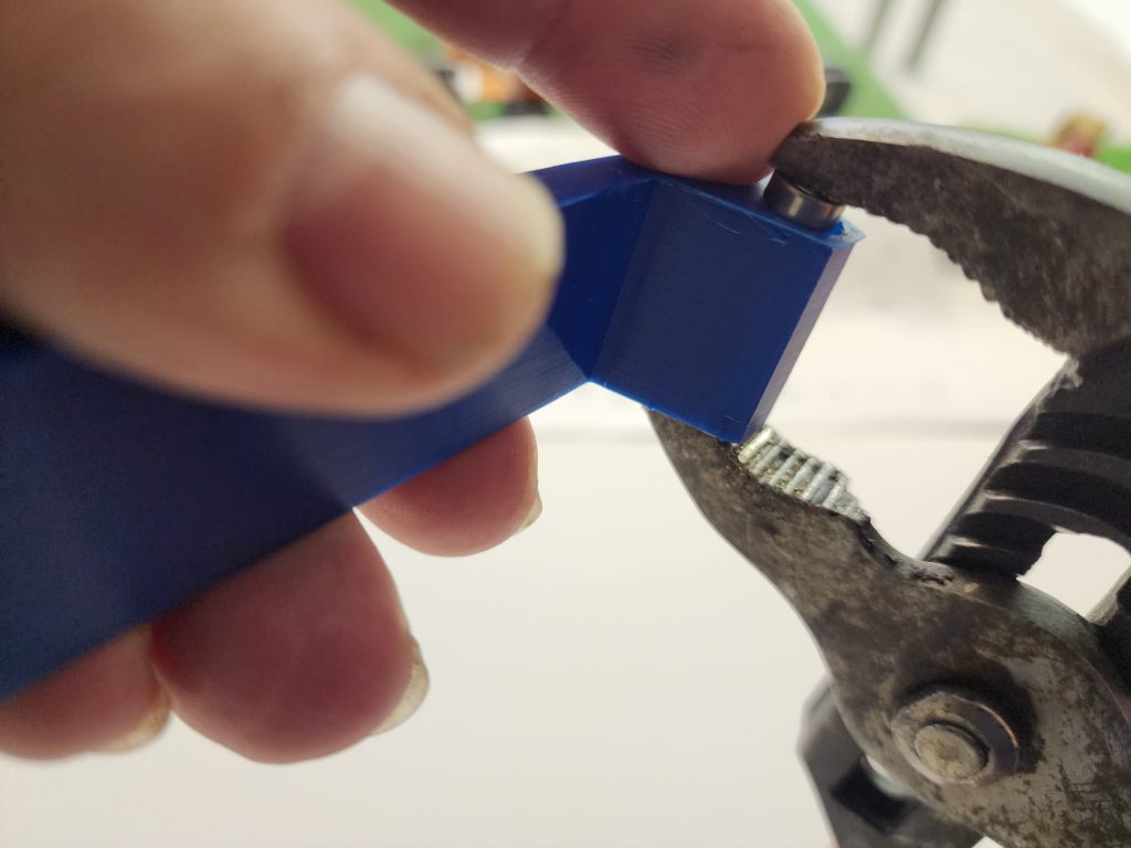
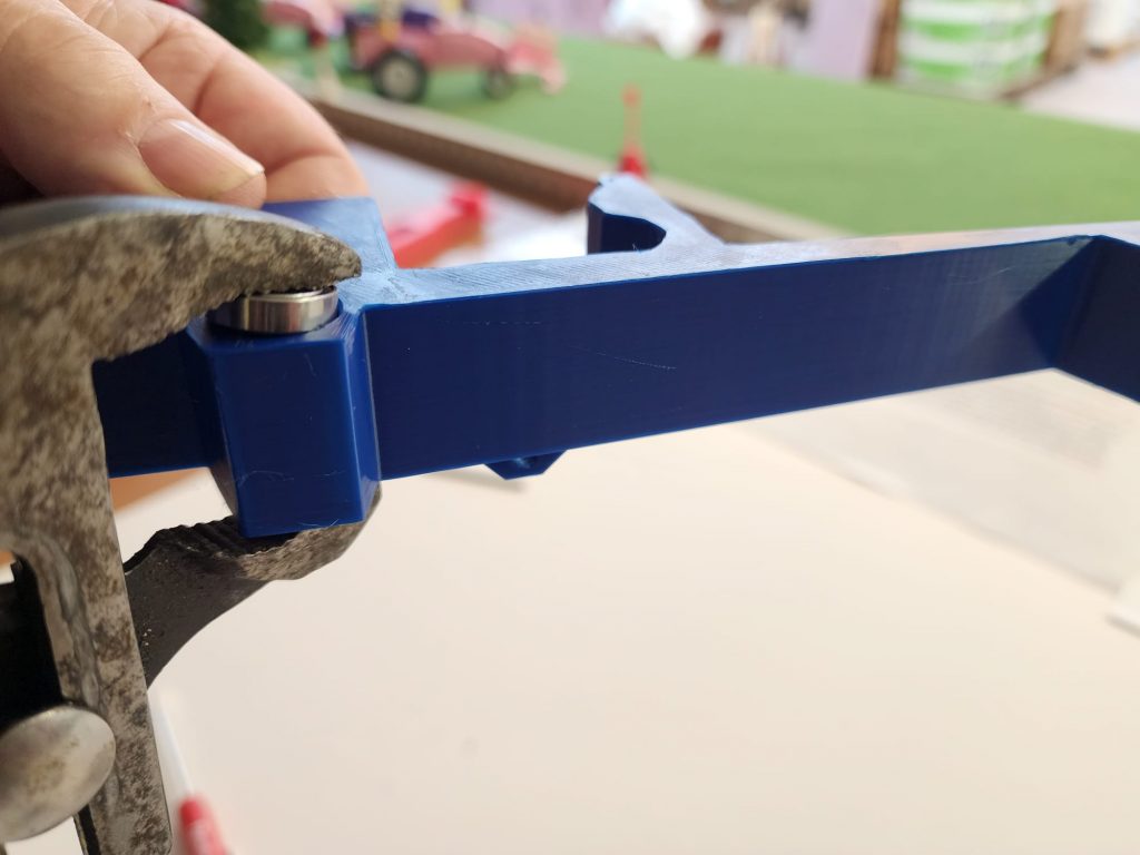
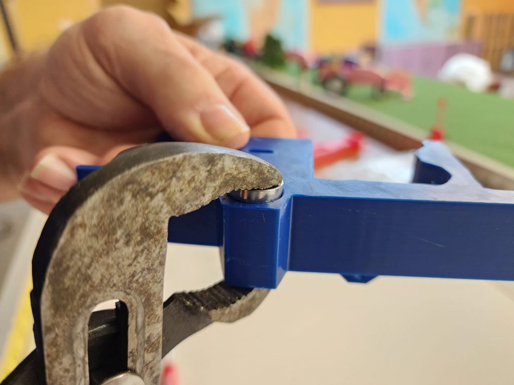
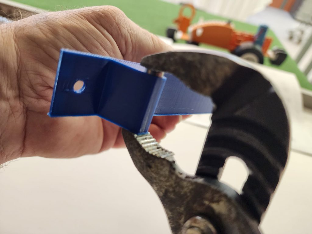
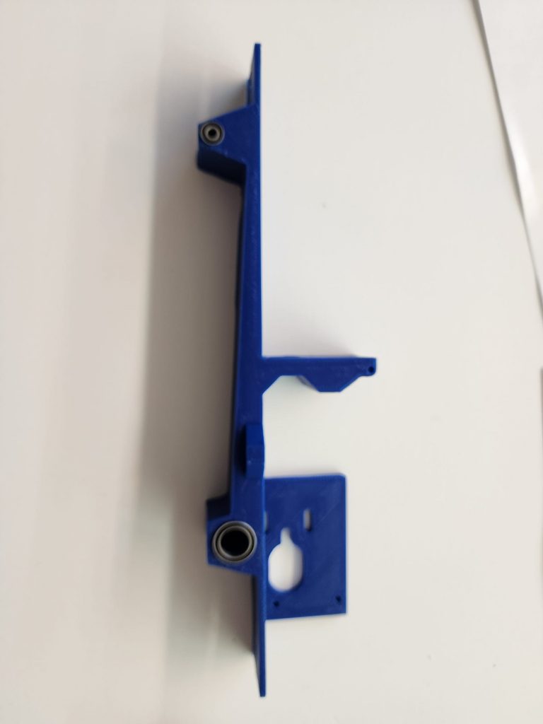
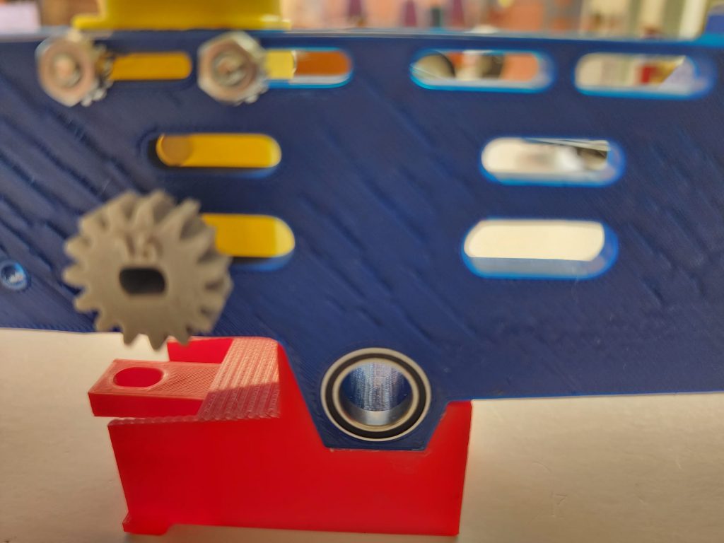
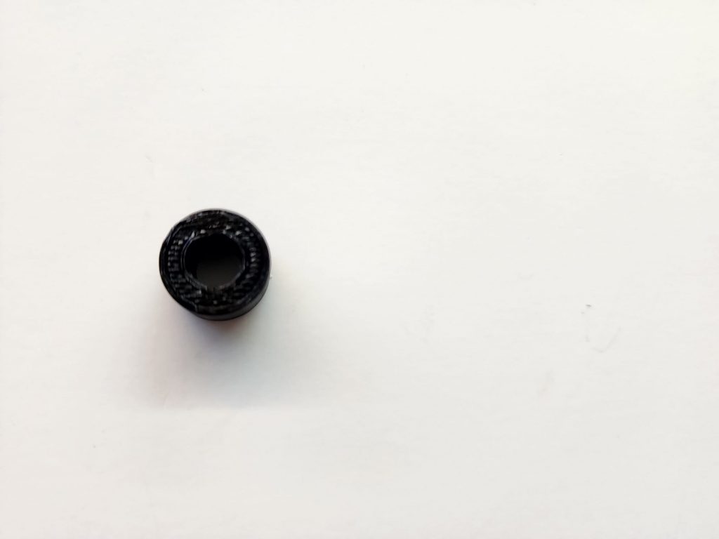
Press the axle bearings, (#2 and #3), in their respective places of the frame, (#1). This may work best using a bench vice or the spindle of a drill press with a dowel mounted in the chuck if they do not go into place by hand. You may also use slip joint pliers or c-clamp, (see figure #2). Be careful during this process.
Step 2
Step 3
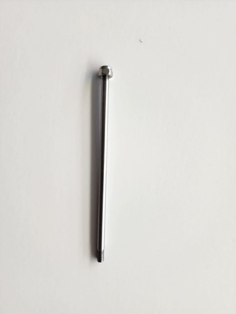
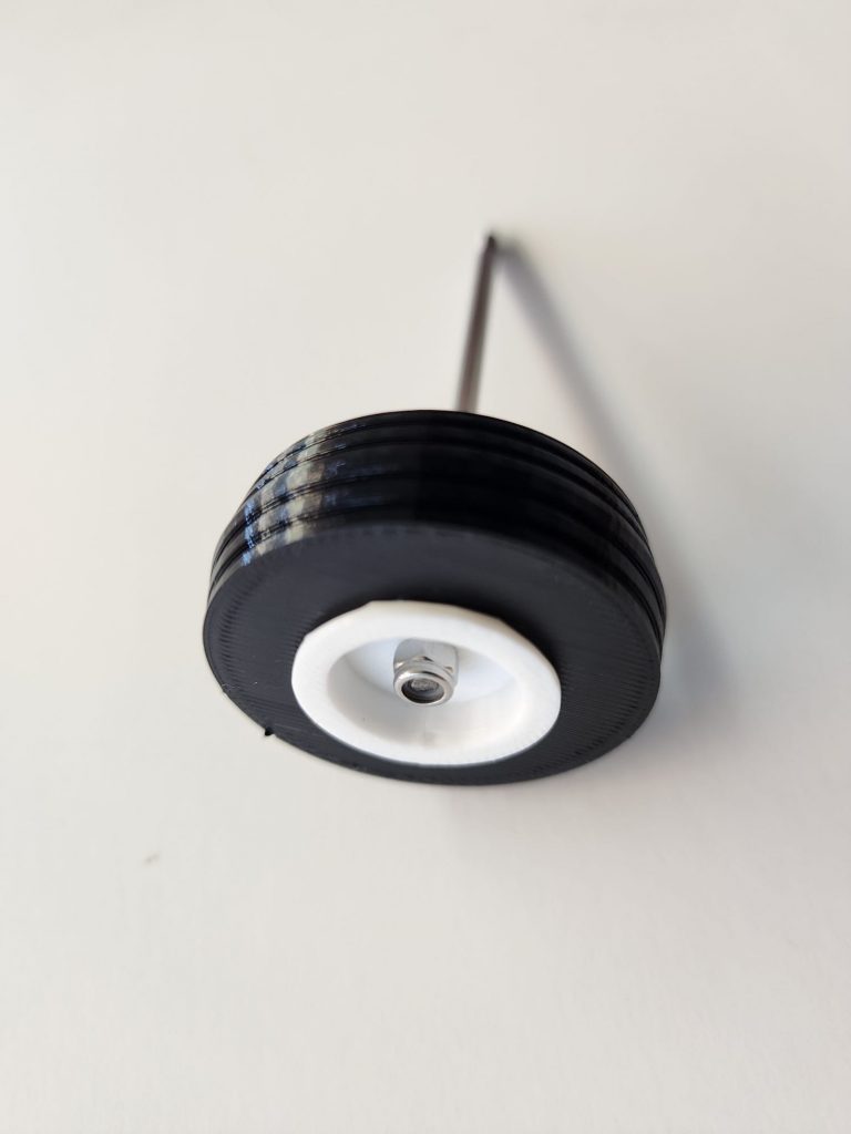
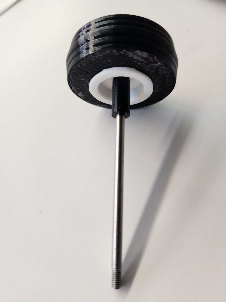
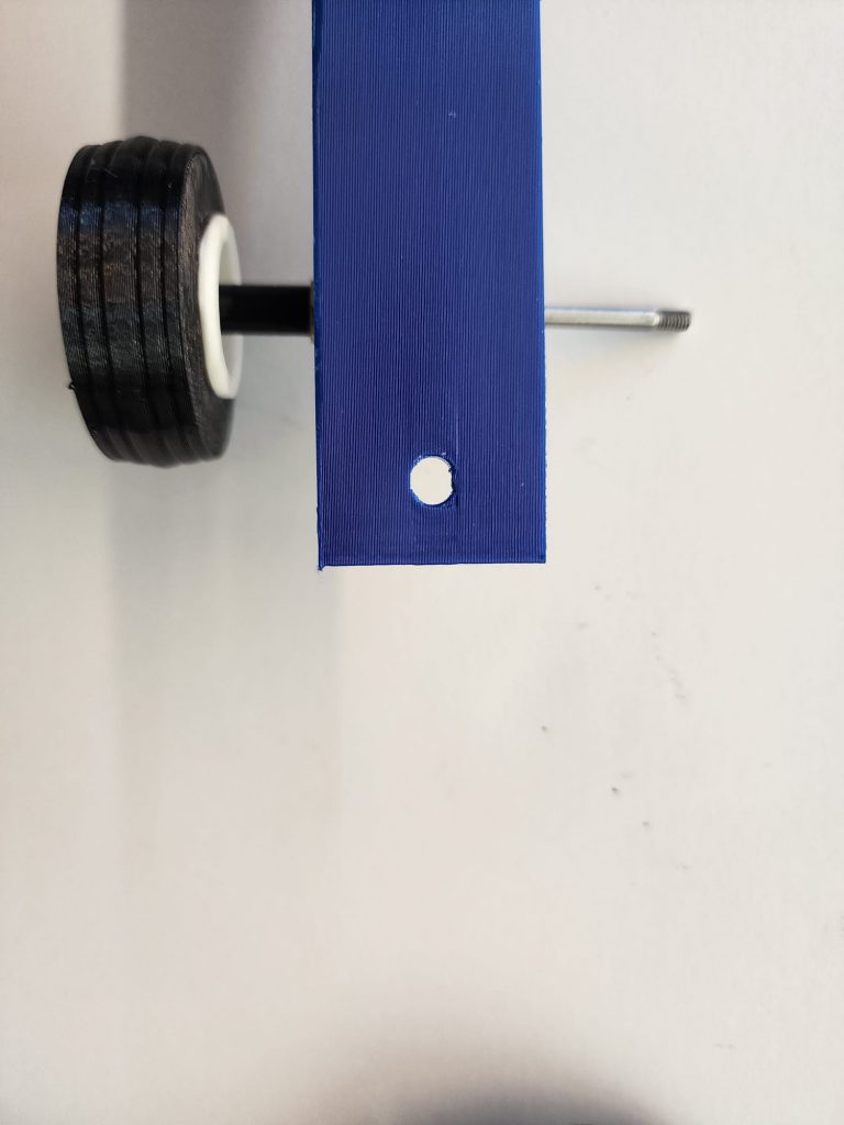
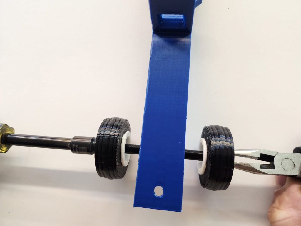
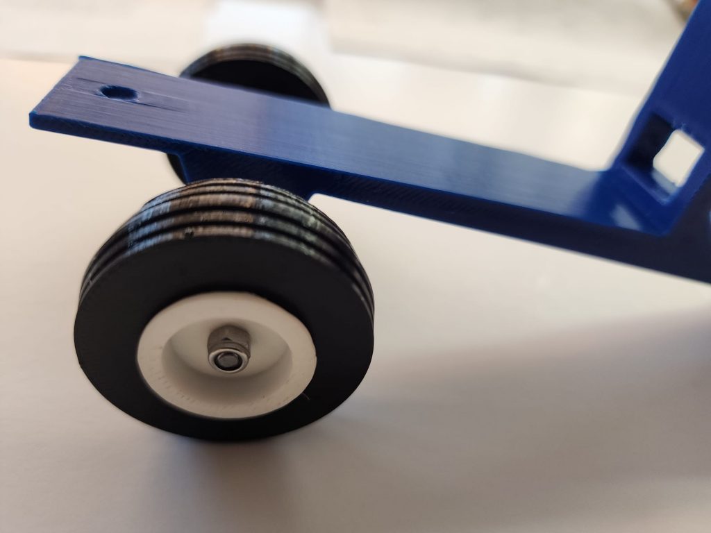
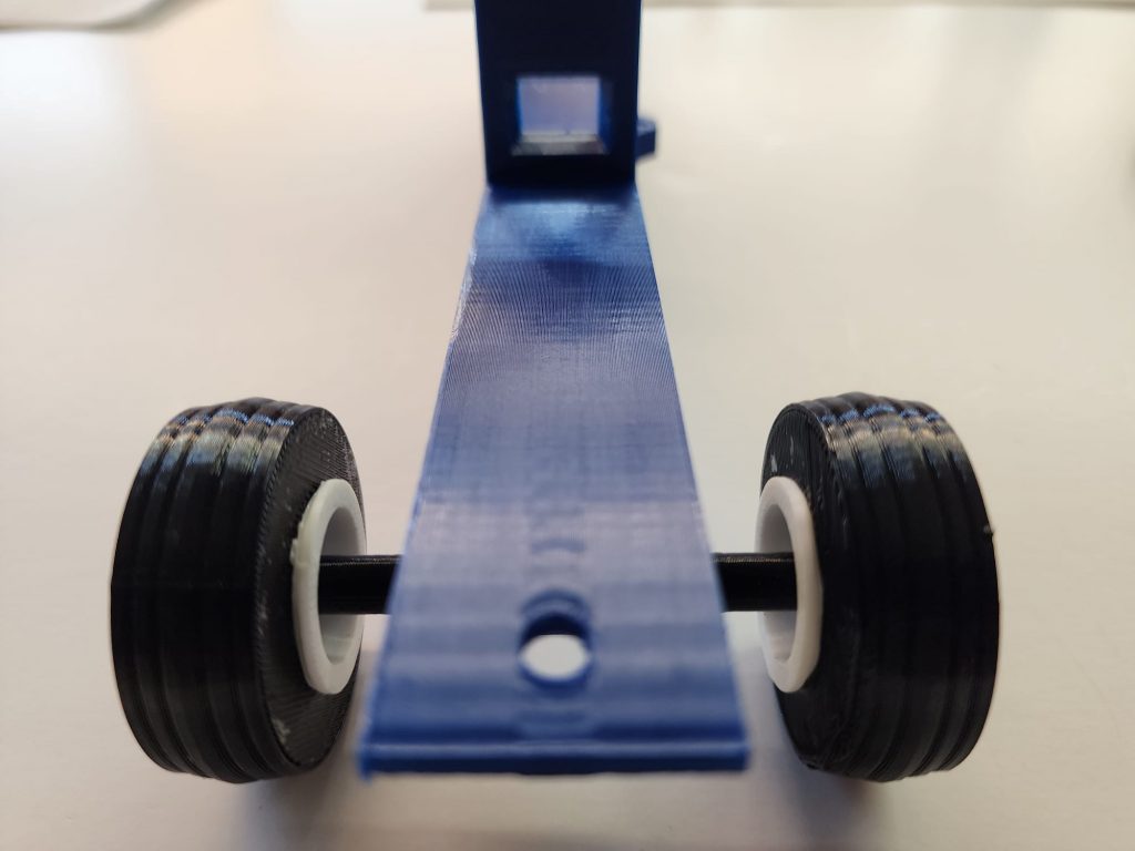
Install one front axle nut, (#22), rims, (#15), tire, (#16), and front axle spacer, (#13) on the front axle, (#14). Then slide that assembly through the front axle bearings installed in step #2. Then install the front axle spacer, rims, tire, and axle nut on the other end of the front axle. Using 5.5 MM nut drivers and/or pliers, adjust the front axle nuts so the front wheels turn freely, (DO NOT OVERTIGHTEN). There should be a small amount of endplay on the entire assembly when adjusted properly, and little or no resistance while rotating the front wheels. (see figure #3)
Step 3
Step 4
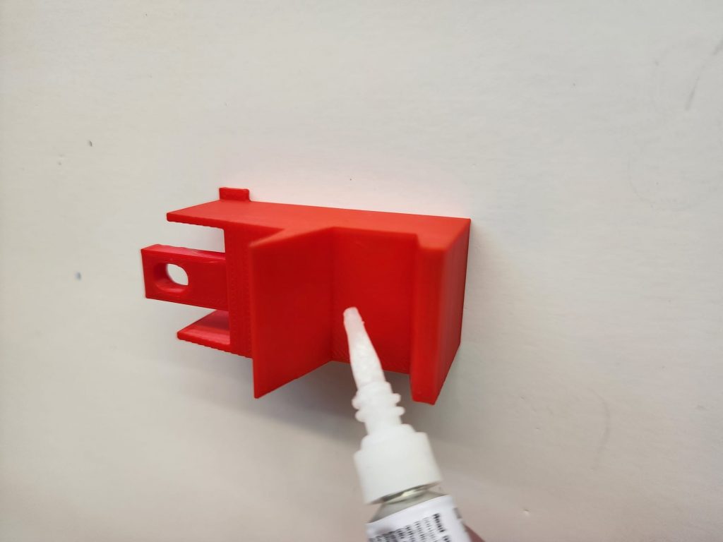
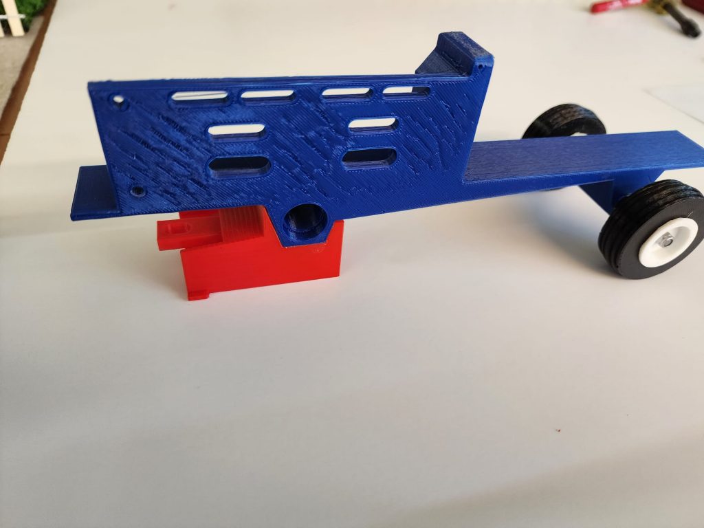
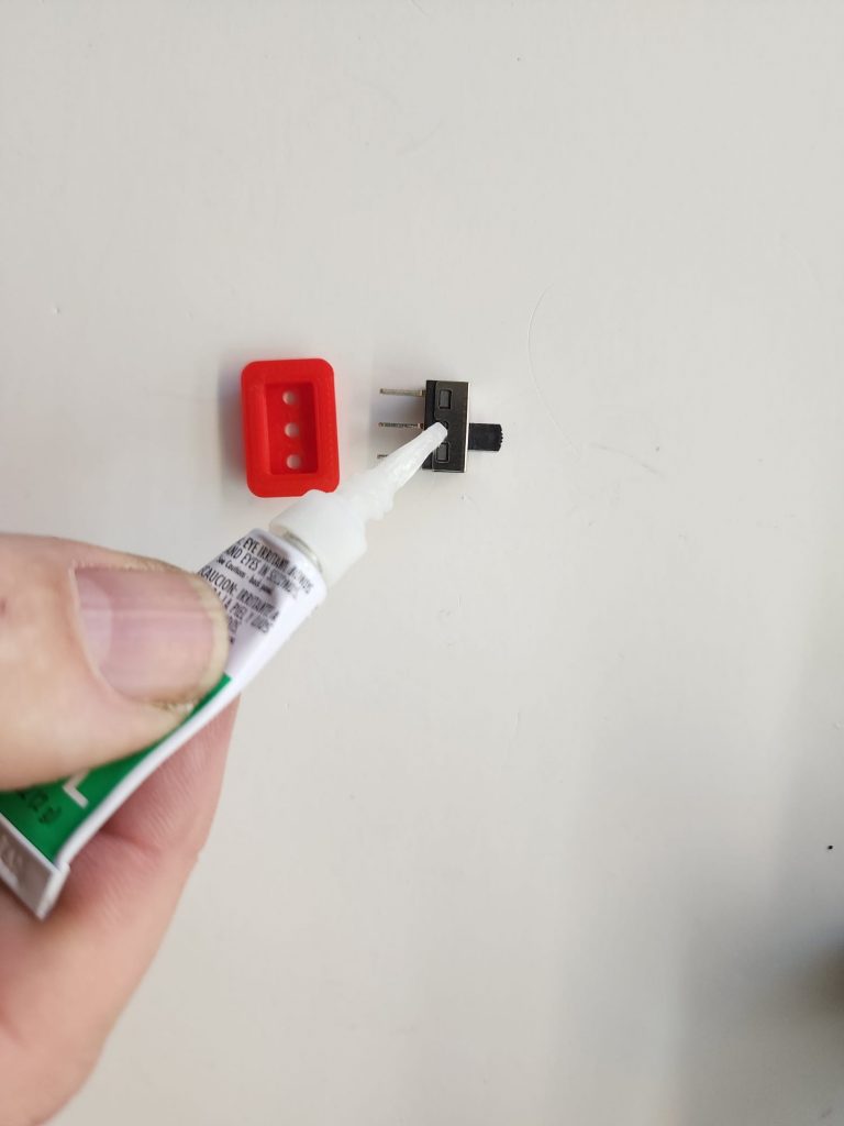
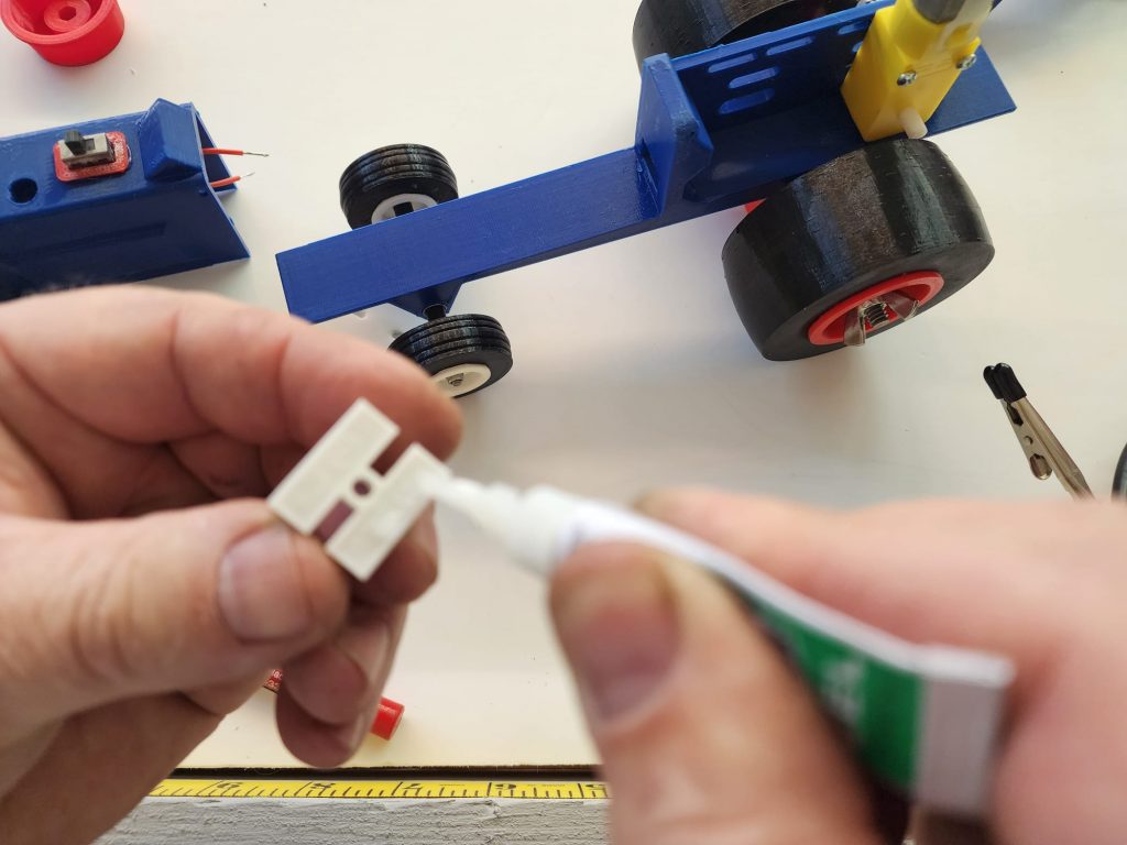
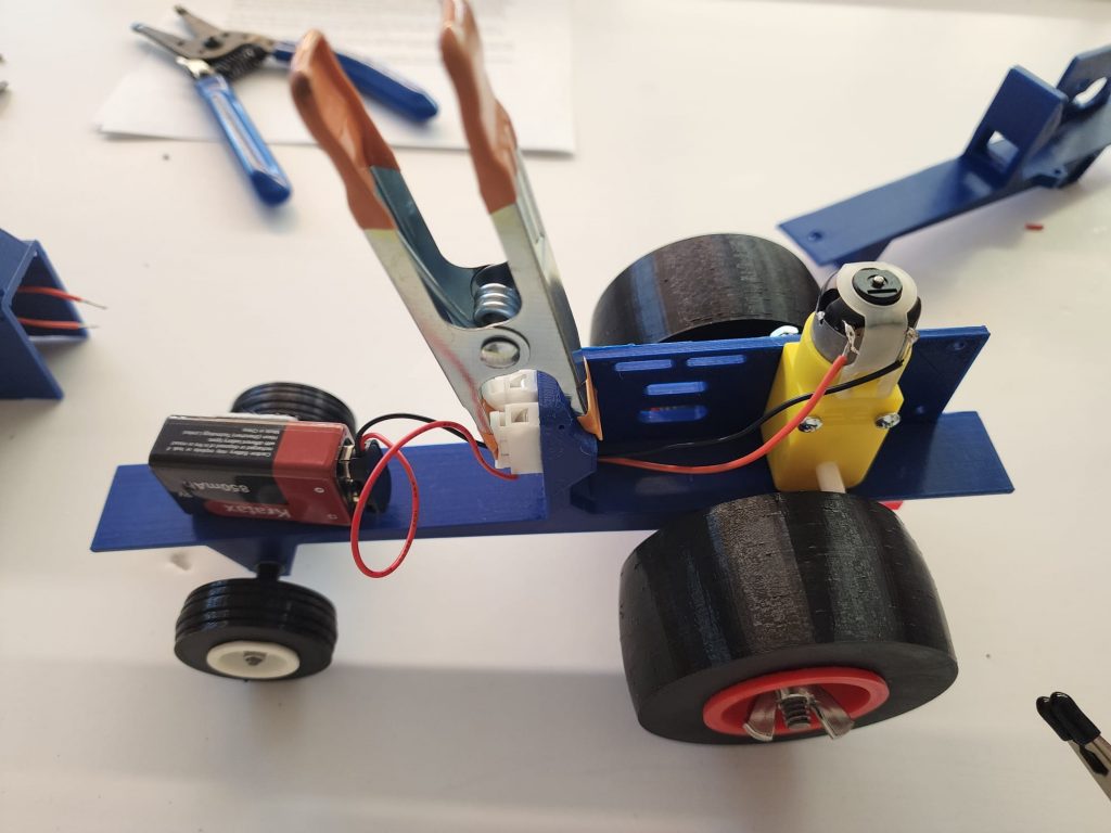
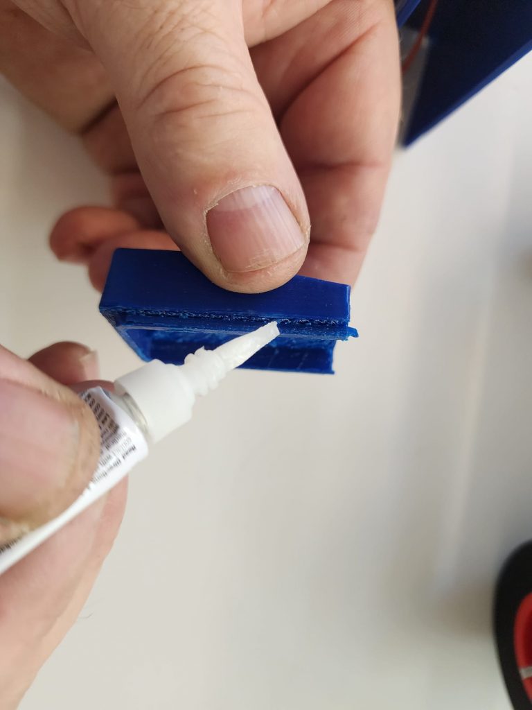
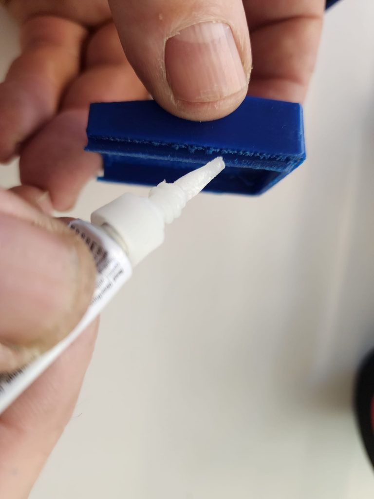
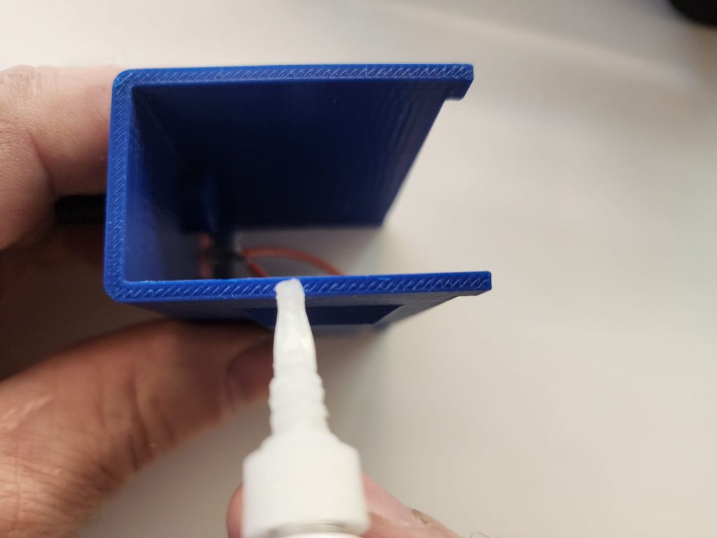
Glue the hitch assembly under the rear axle housing with an appropriate glue, we suggest Loctite super glue ULTRAGEL control. (Available on our website) This product allows for several seconds of repositioning. Once the part is in the correct position, set the model upright on the front wheels and the bottom of the hitch assembly, (see figure #4). Place 1 to 2 pounds of weight centered over the hitch assembly and allow the proper fixture or clamp time per the glue instructions. You may want to glue the terminal block, (#30) into the shallow recess on the front side of the dash at this time too. (figure #5).
Step 4
Step 5
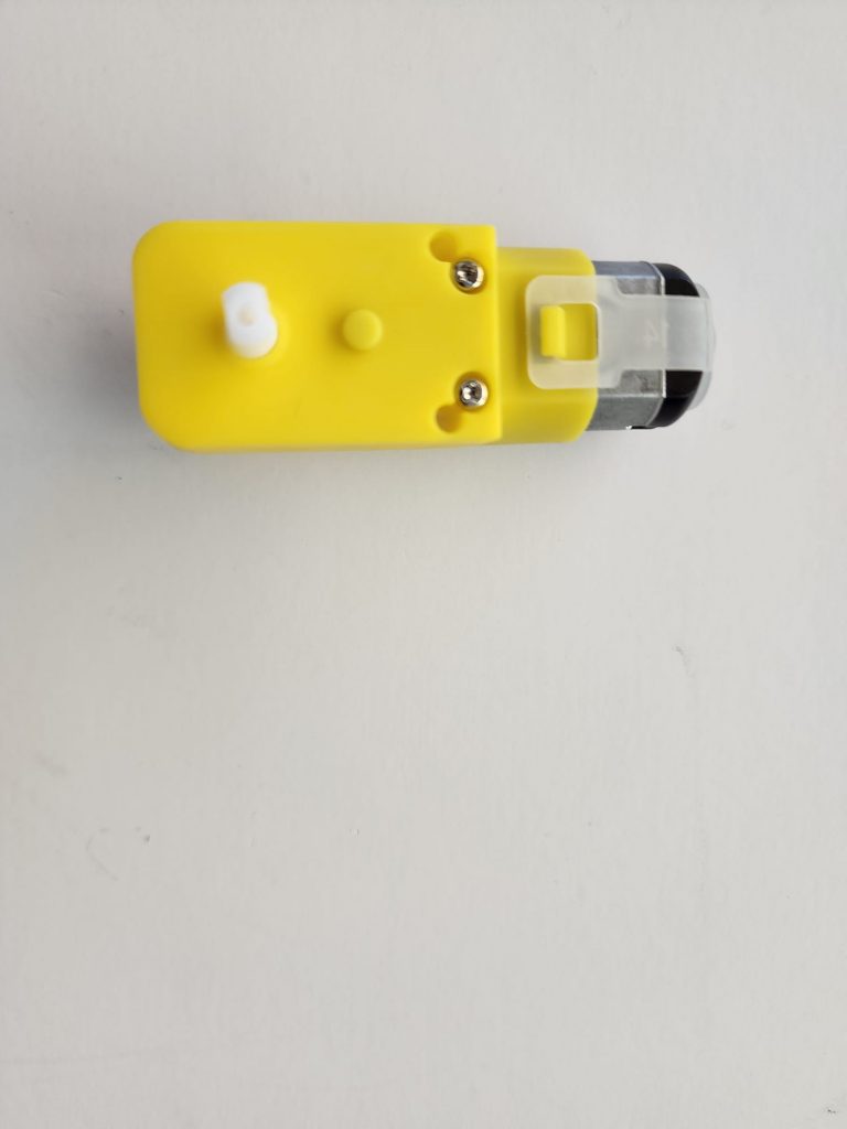
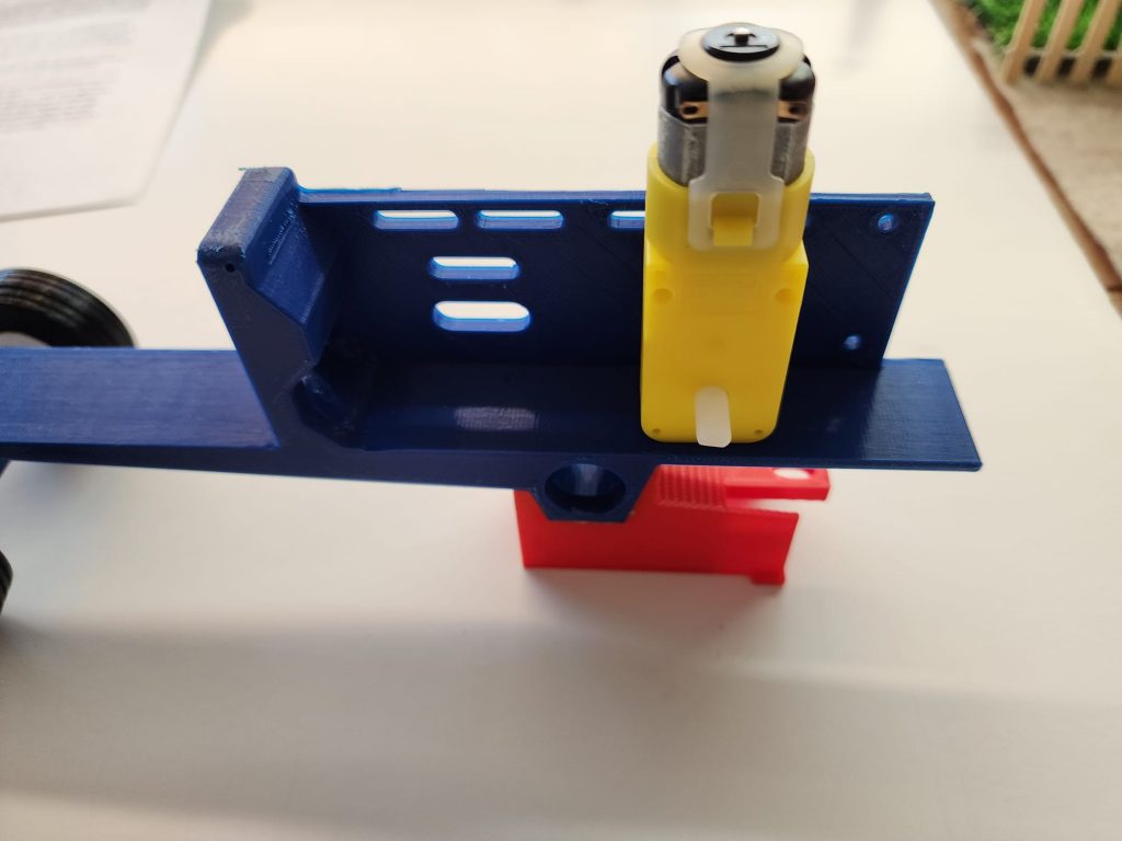
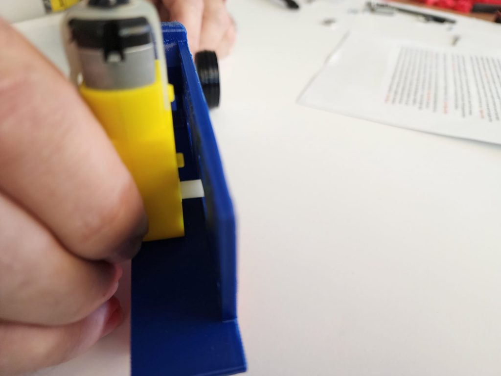
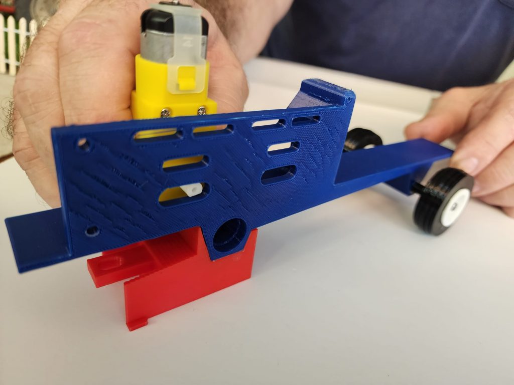
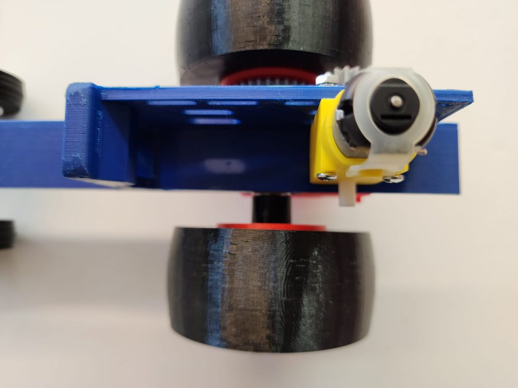
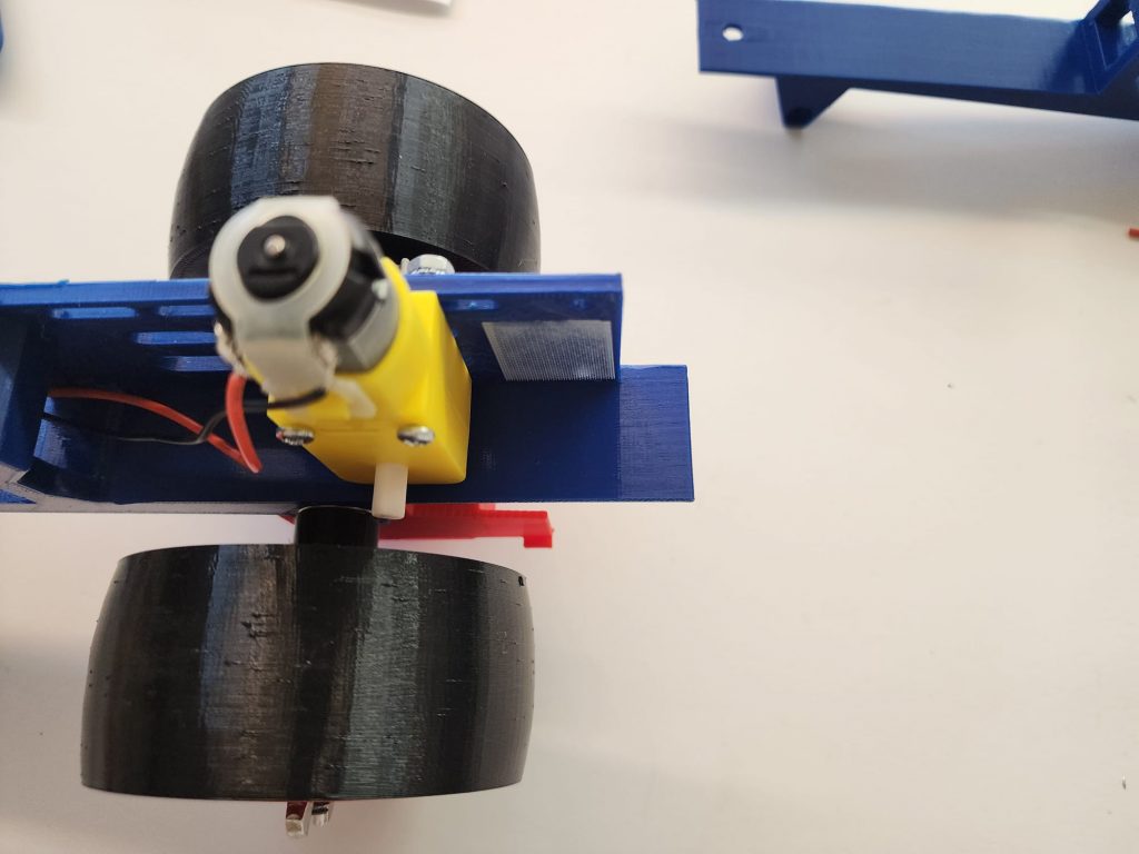
Next install the gearmotor using the 4-40 x 1 1/8” screws and star washer/nuts. Leave the screws loose for now. There is a small locating button on one side of the gearbox, put this side of the gearmotor towards the frame, (see figure #6). Be sure to push the gearmotor to its rearward most position.
Step 5
Step 6
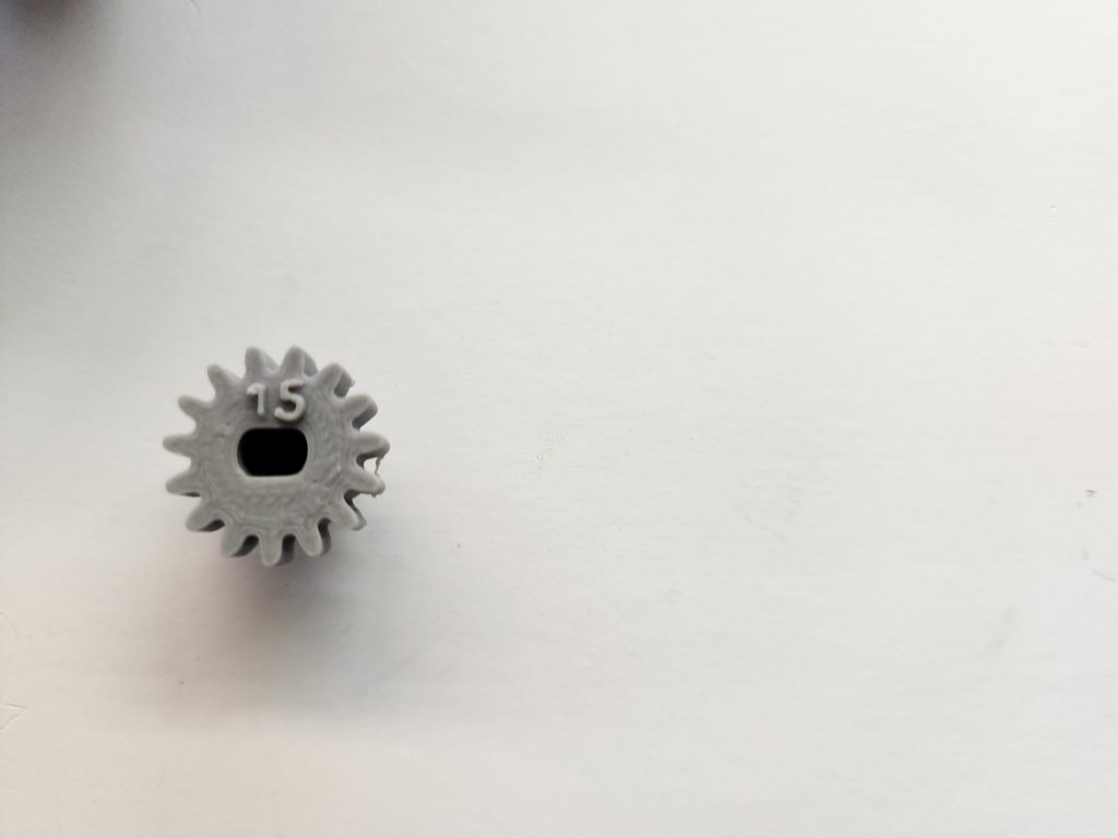
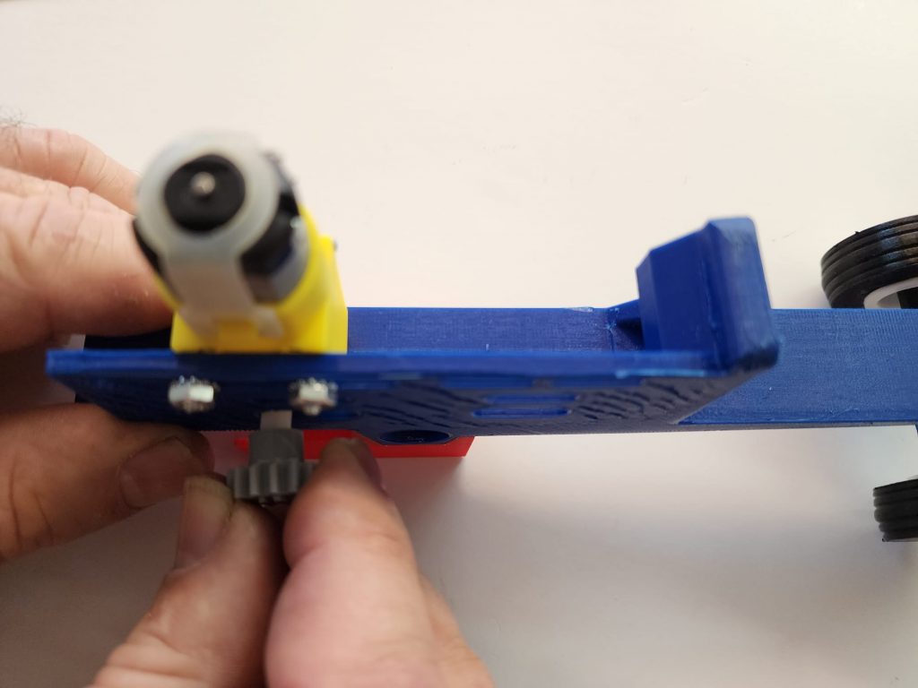
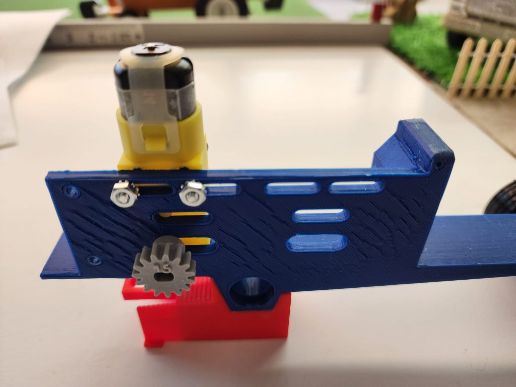
- Press the pinion gear, (#7) of your choice onto the output shaft of the gearmotor, (#4), (see figure #7).
Step 6
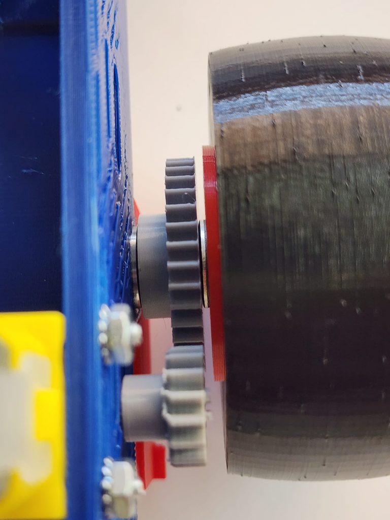
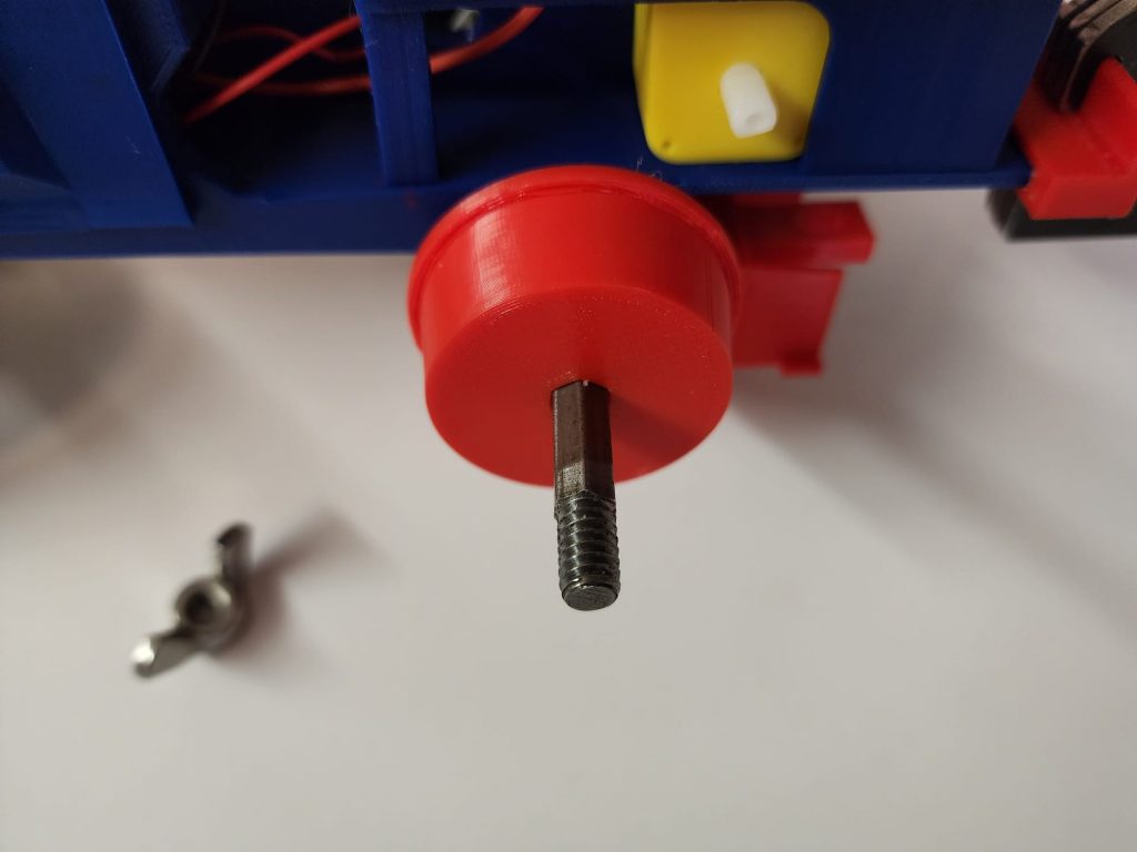
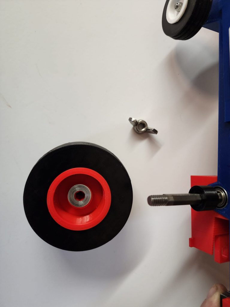
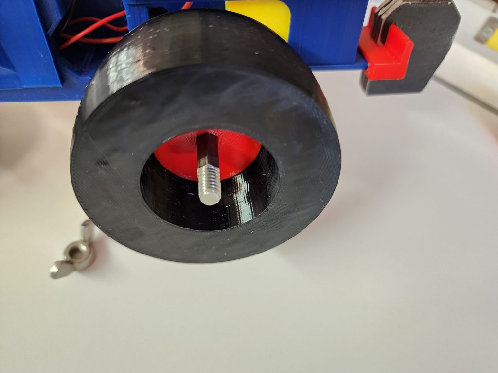
Step 7
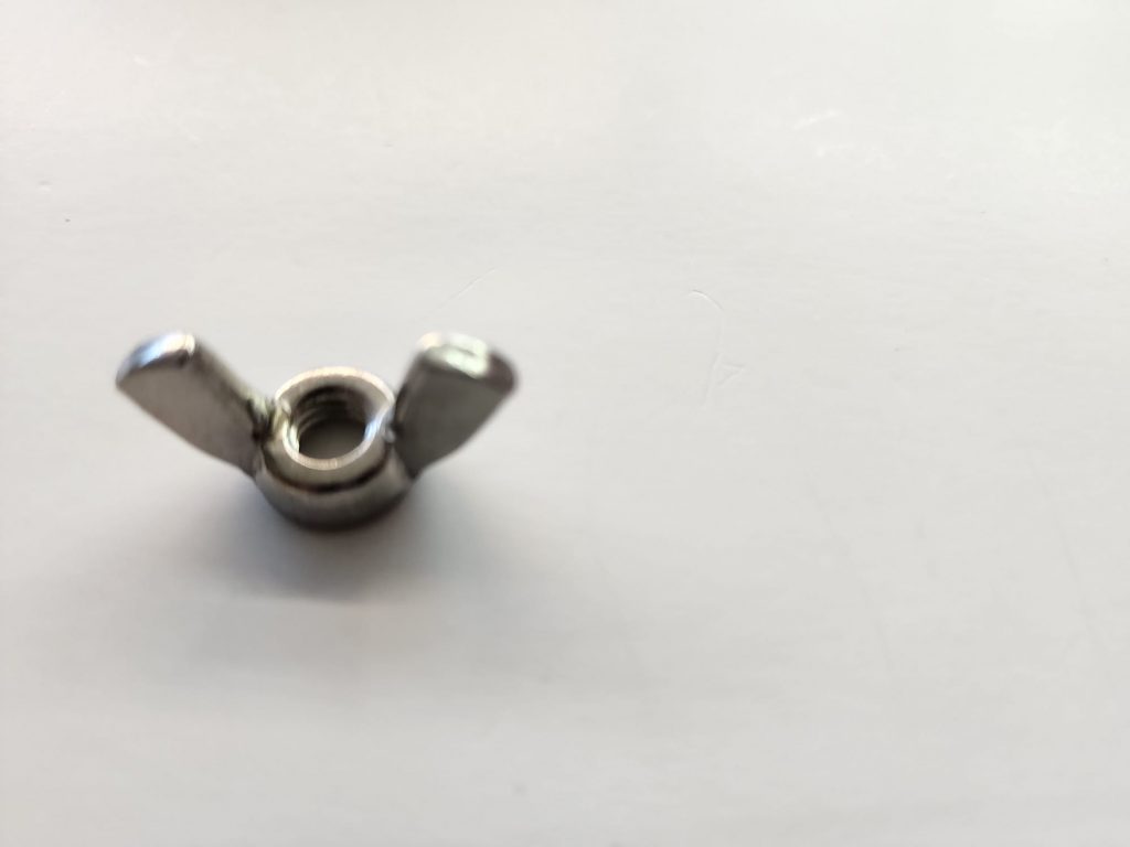
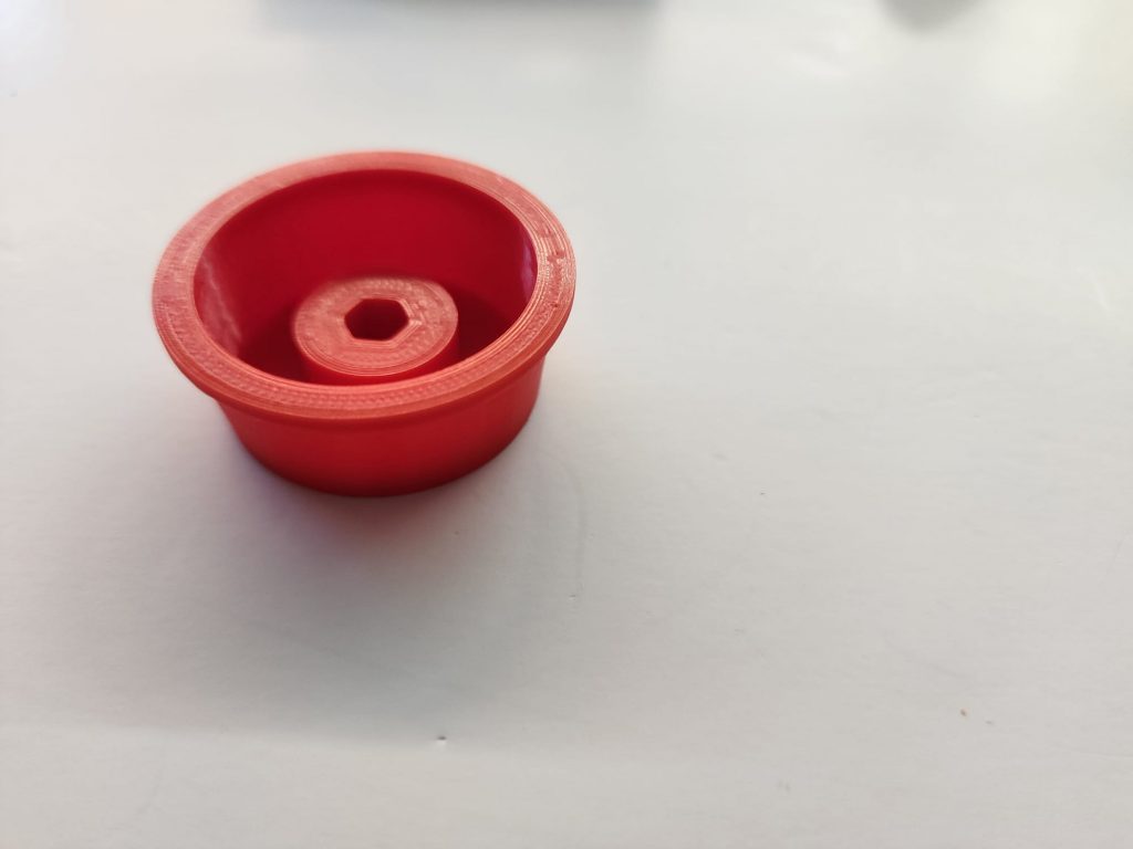
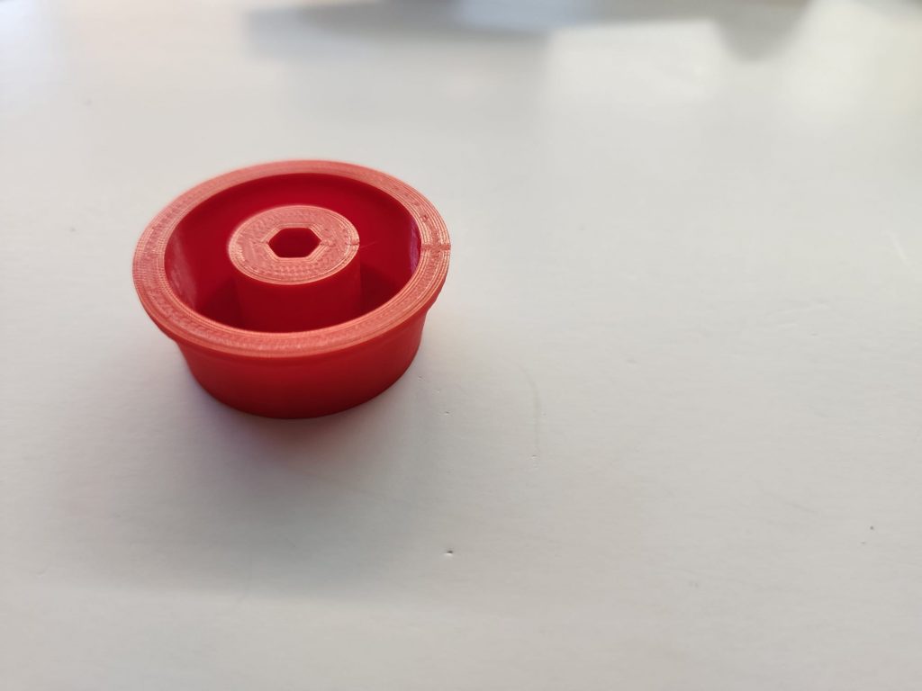
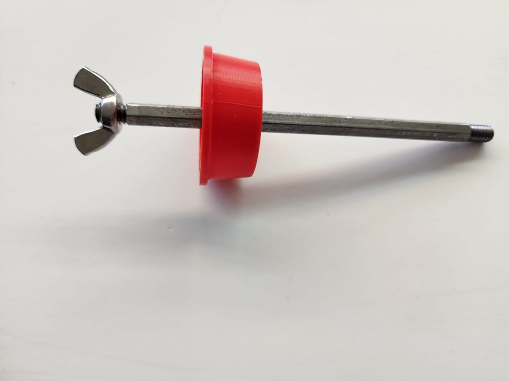
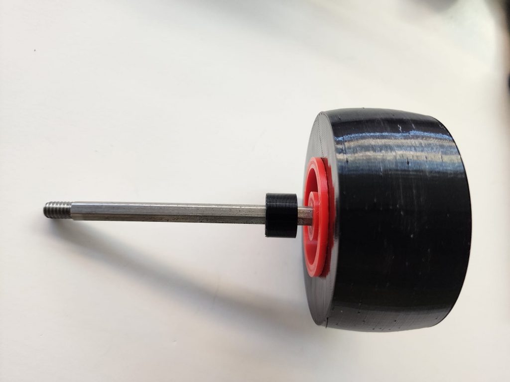
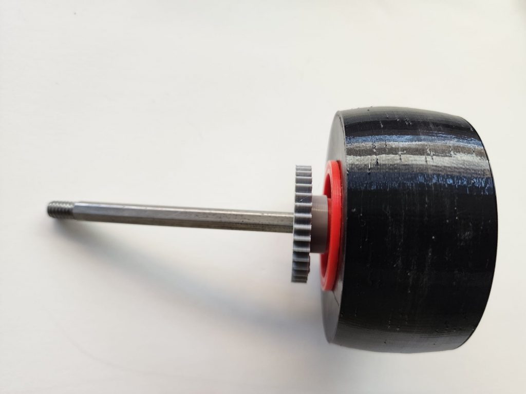
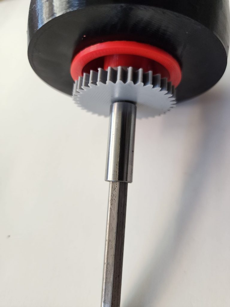
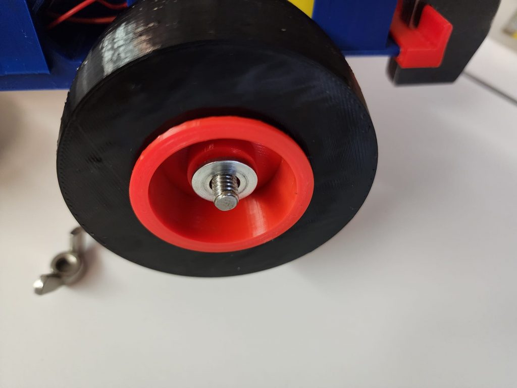
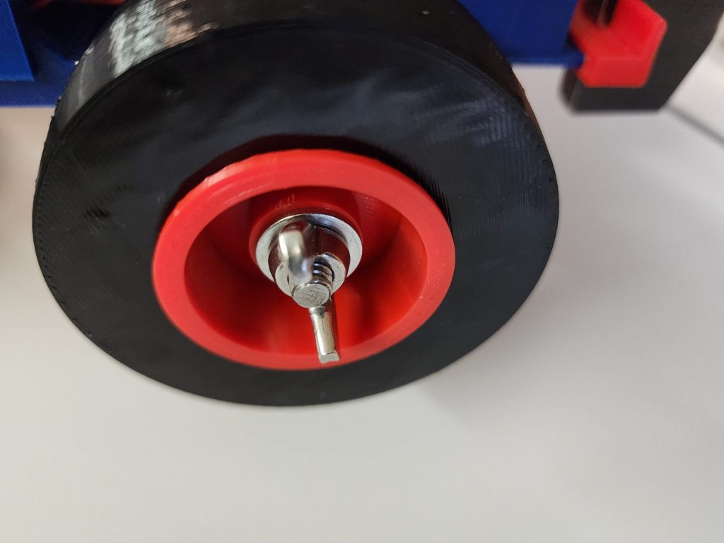
Install a wingnut, (#20) outer rear rim, (#12), (this is the one where the hub is recessed below the rim face, (see figure #8), tire, (# 11), inside rim, (#9), (with a flush hub and rim face, (figure #9), and your choice of planetary gear, (#8), and the axle hex adaptor, (#6) onto the rear axle (#5). From the right side of the tractor as viewed from the back, slide this assembly through the rear axle bearings installed in step #2. On the other side of the frame install the axle spacer, (#10), inside rim, tire, outside rim, and wing nut. Again, (DO NOT OVERTIGHTEN). There should be a small amount of endplay when the axle nuts are adjusted properly. It may be necessary to install one of the ¼" flat washers supplied, between the frame and the planetary gear to get it to line up with the pinion gear on the gearmotor. (See figure #10).
Step 7
Step 8
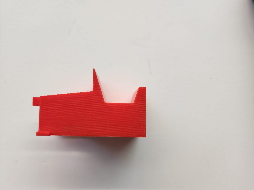
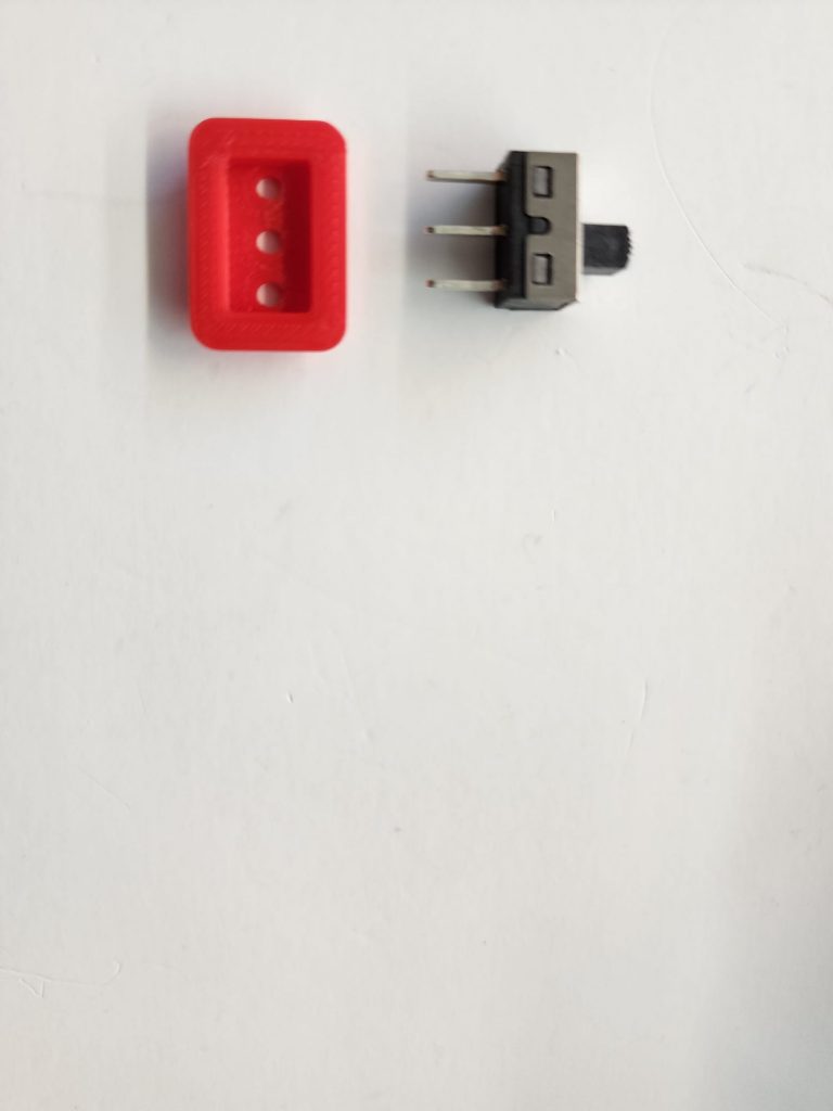
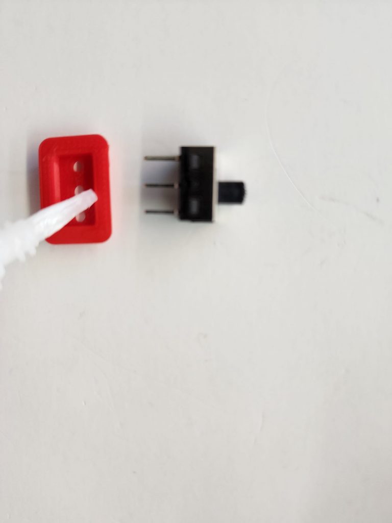
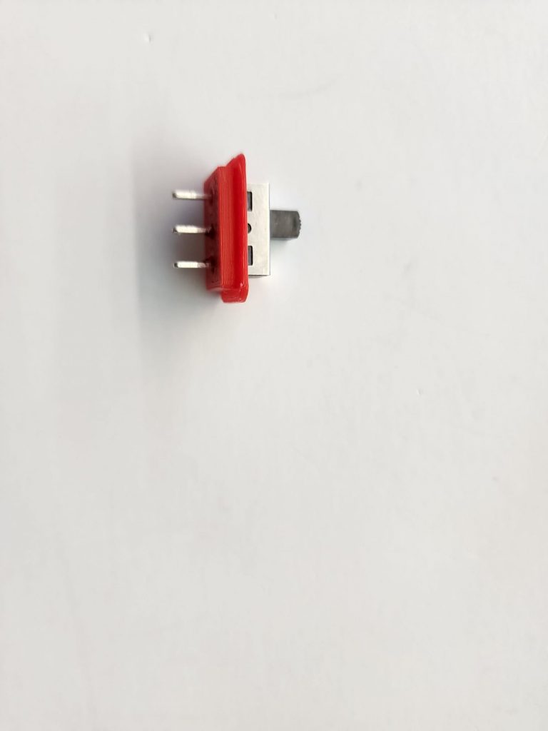
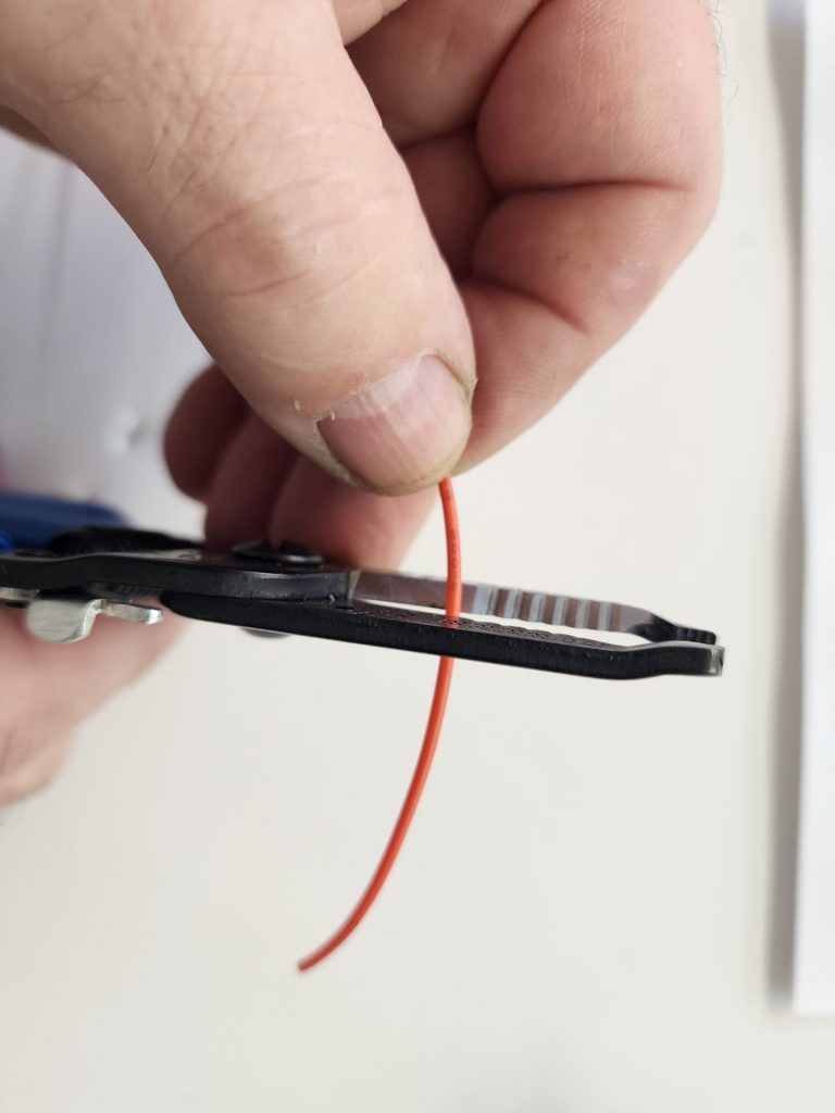
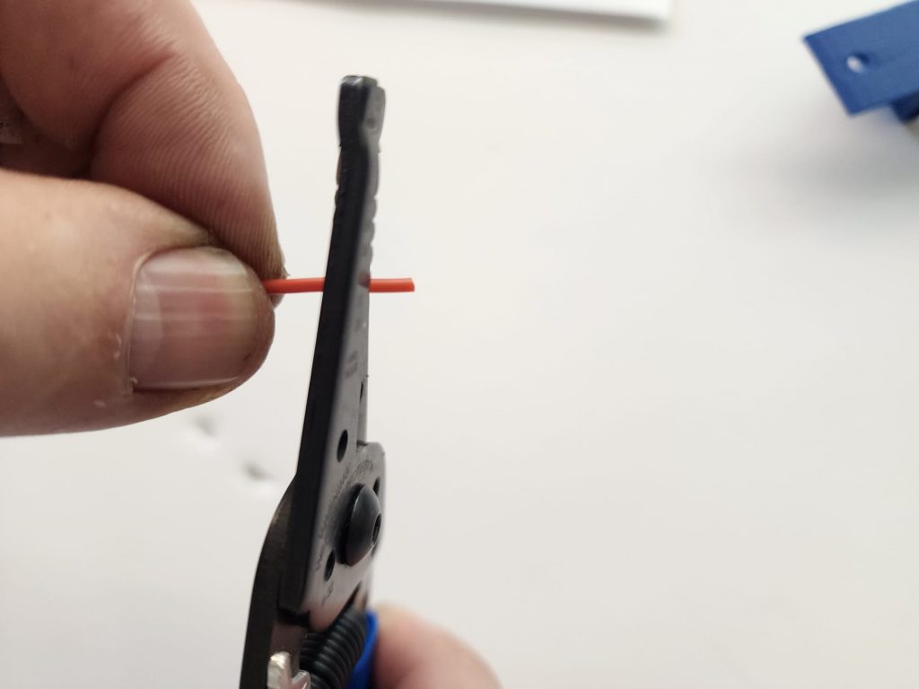
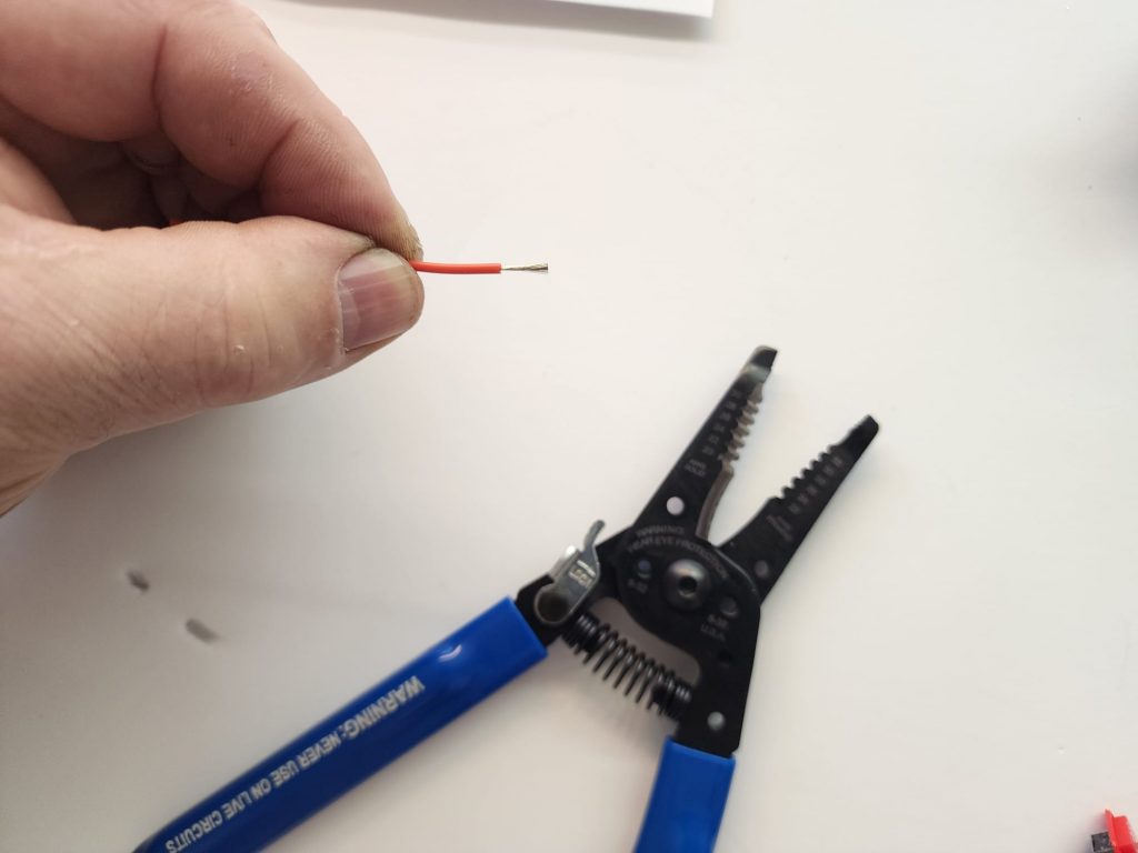
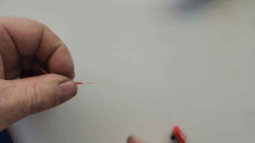
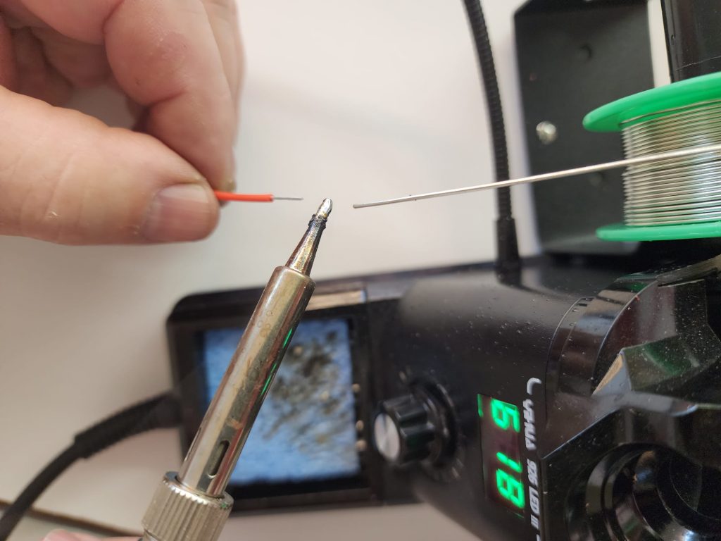
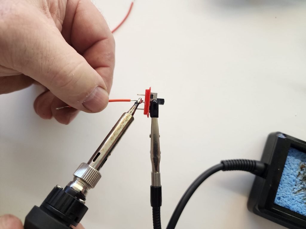
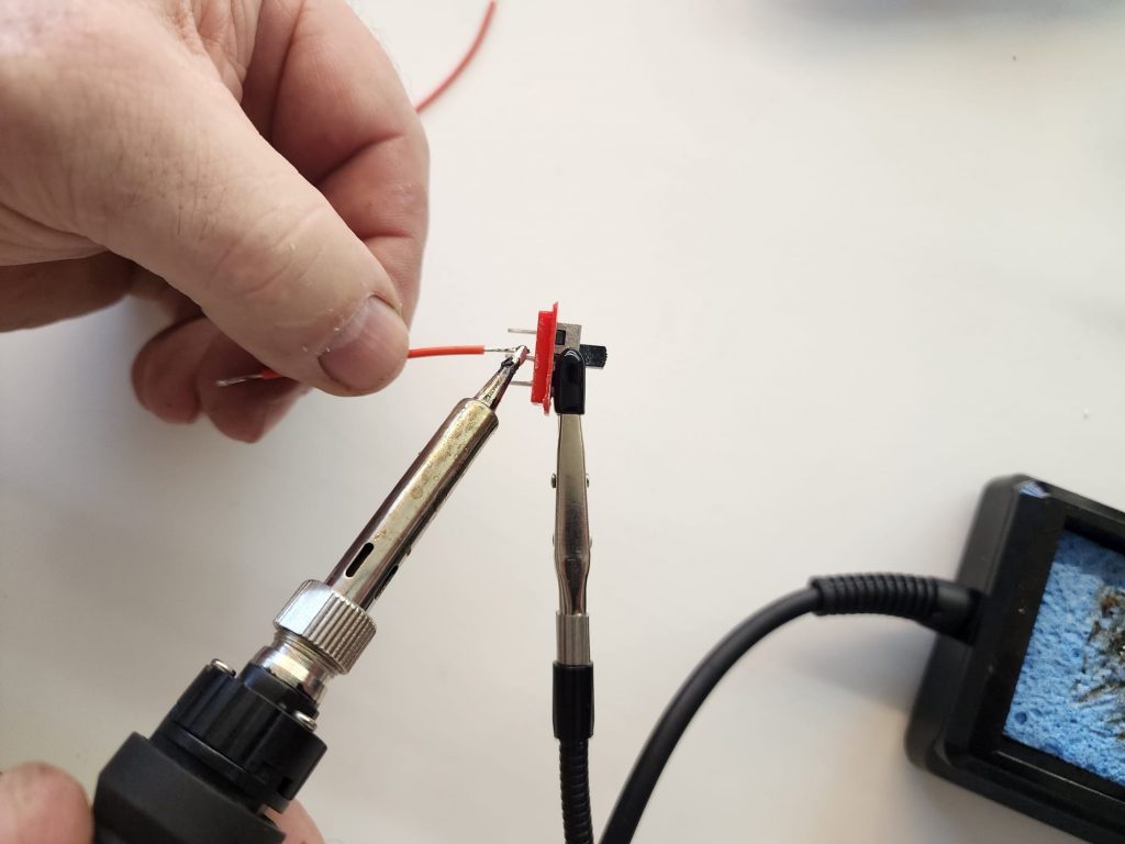
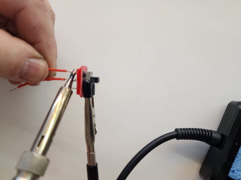
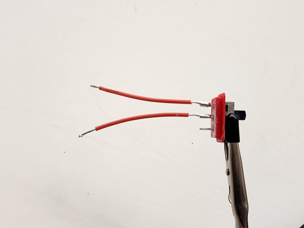
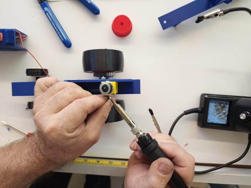
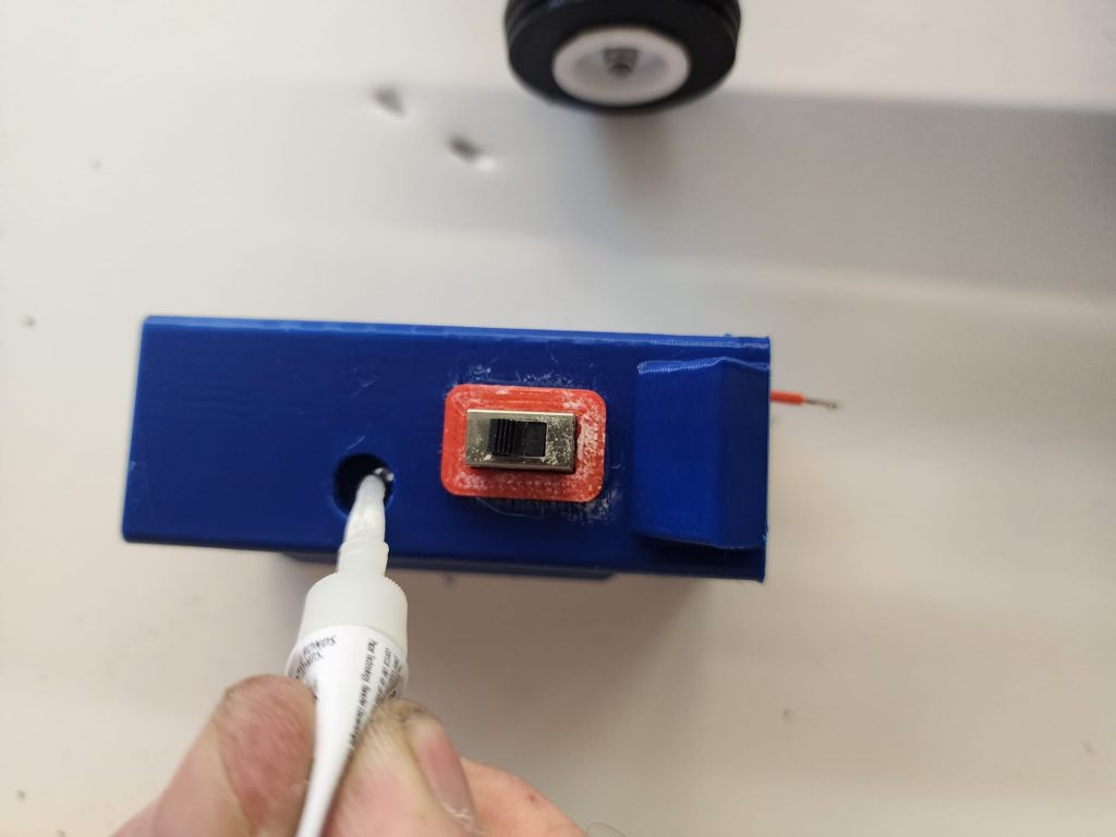
Glue the switch, (#29) into the recess of the switch housing, (#27). The switch closes the circuit between the center pin and an end pin when it is in position towards either pin. Cut 2 red wires about 2 inches long. Using wire strippers, remove about 3/8” insulation on each end. Tin and solder these wires onto the switch, one on the center pin and one on another pin. (See figure #11 Wiring Diagram). Also see our Soldering video on mechtechmodels.com, for hints/instructions on tinning/soldering. You can also purchase soldering tools/supplies on the website.
Step 8

Step 9
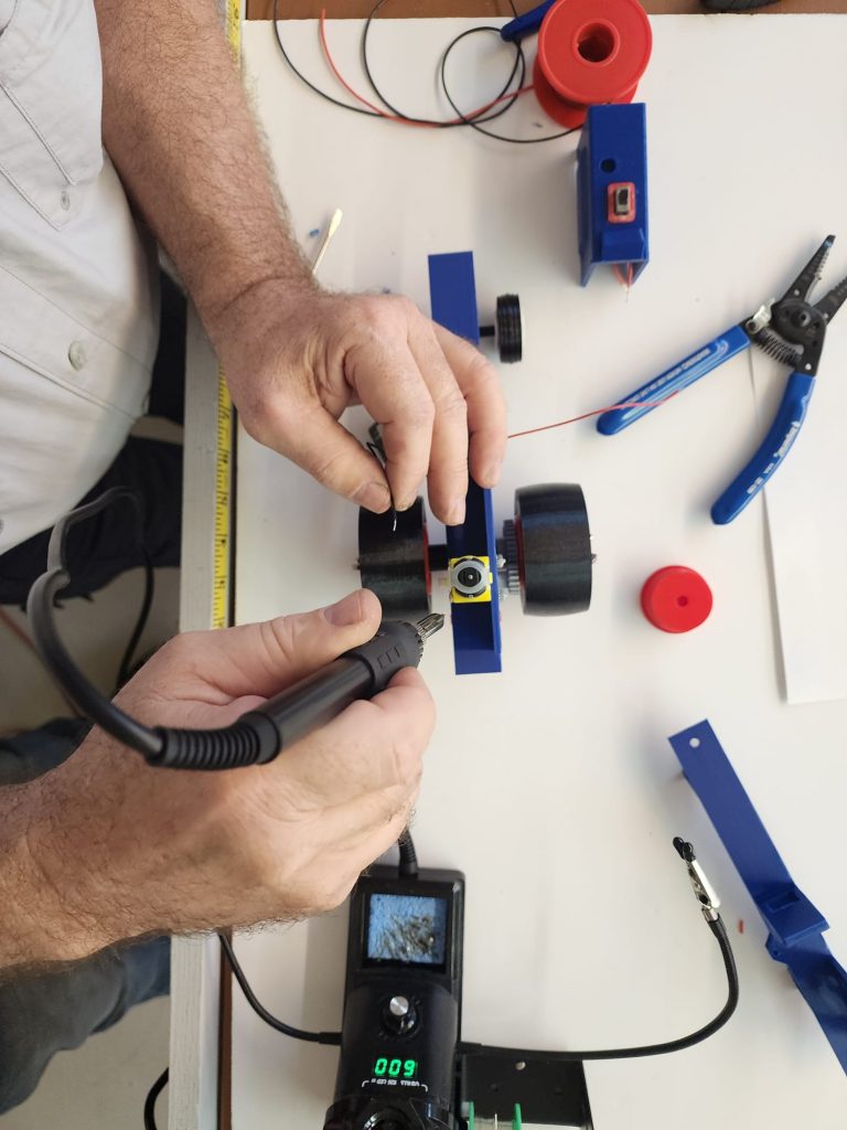
Block the tractor wheels up so they can spin freely by placing a block under the hitch assembly. Locate the battery connector and install it on a battery. Touch the lead wires to the terminals of the motor. Note the direction the rear wheels spin. You may have to reverse the wires to get the wheels to spin in the forward direction. Mark the terminal the red wire was connected to when the wheels spun in the right direction, this will be your positive or red wire soldering position.
Step 9
Step 10
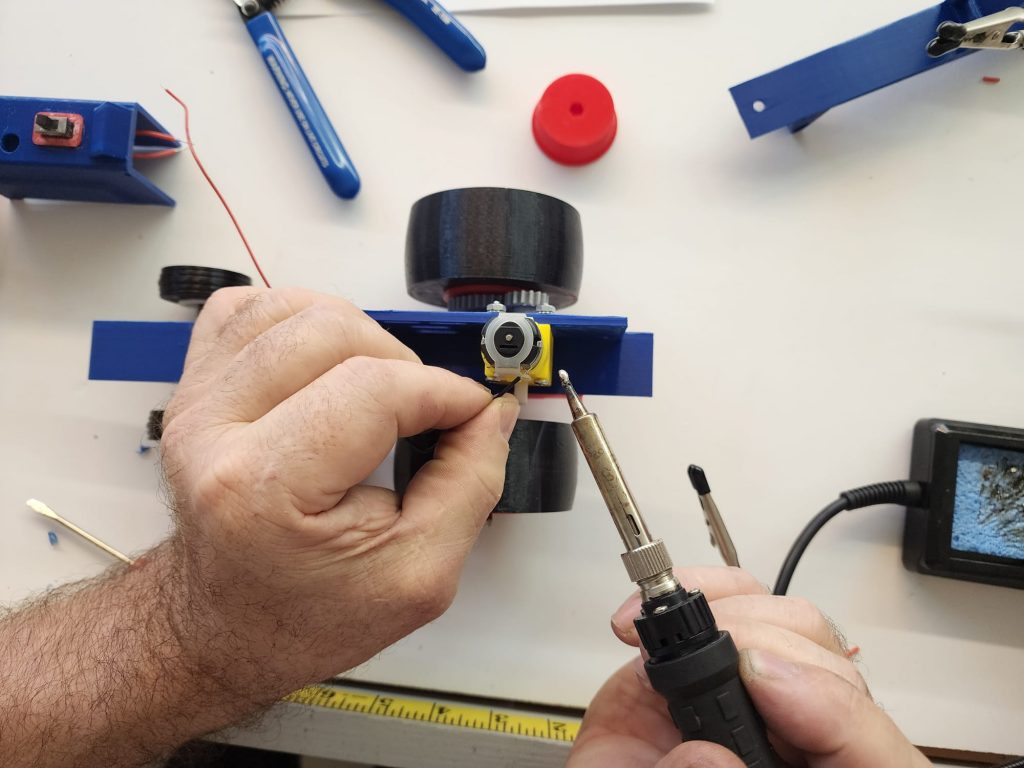
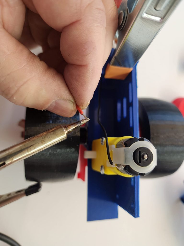
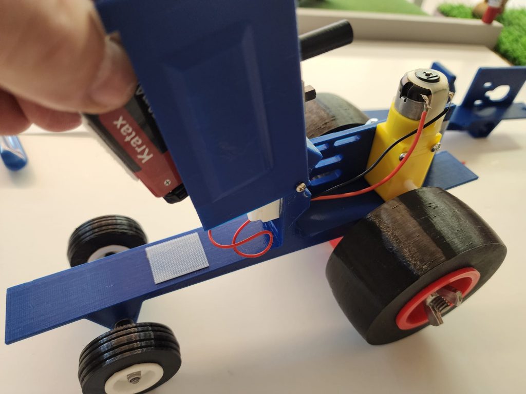
The battery, (#32) may be used as movable ballast, so it may sit in the back near the motor, or under the hood/body. There should be just enough wire length on the battery connector to allow for either position. Cut/strip/tin/solder a red wire to the motor, the other end clamps into the bottom of the terminal block, run the wire through the rectangle hole in the dash. Tin the end of the wire going to the terminal block.
Step 10
Step 11
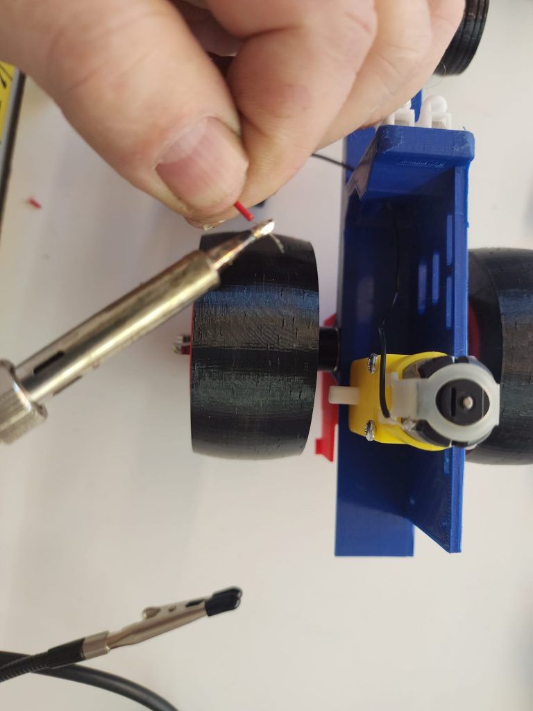
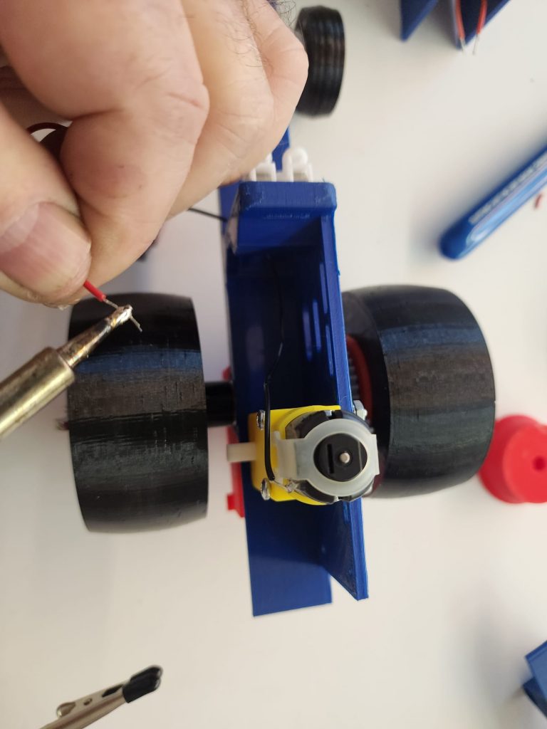
Tin/solder the black wire of the battery connector, (#31) to the other motor terminal. (Hint, the connector can pass through the rectangular hole in the dash for handy re-positioning of the battery). Strip/tin the red wire and connect it to the other bottom clamp of the terminal block.
Step 11
Step 12
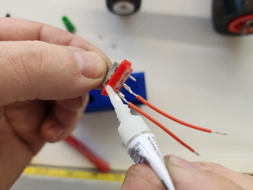
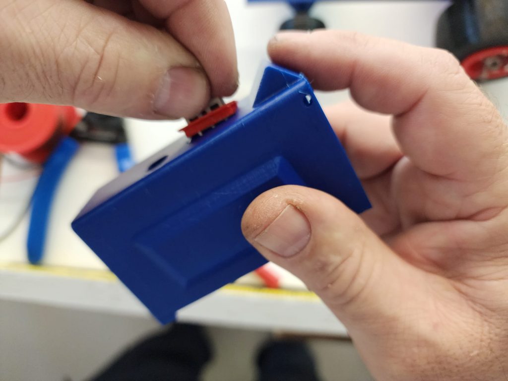
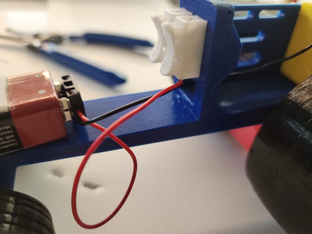
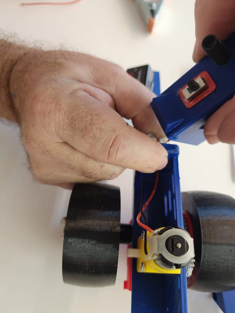
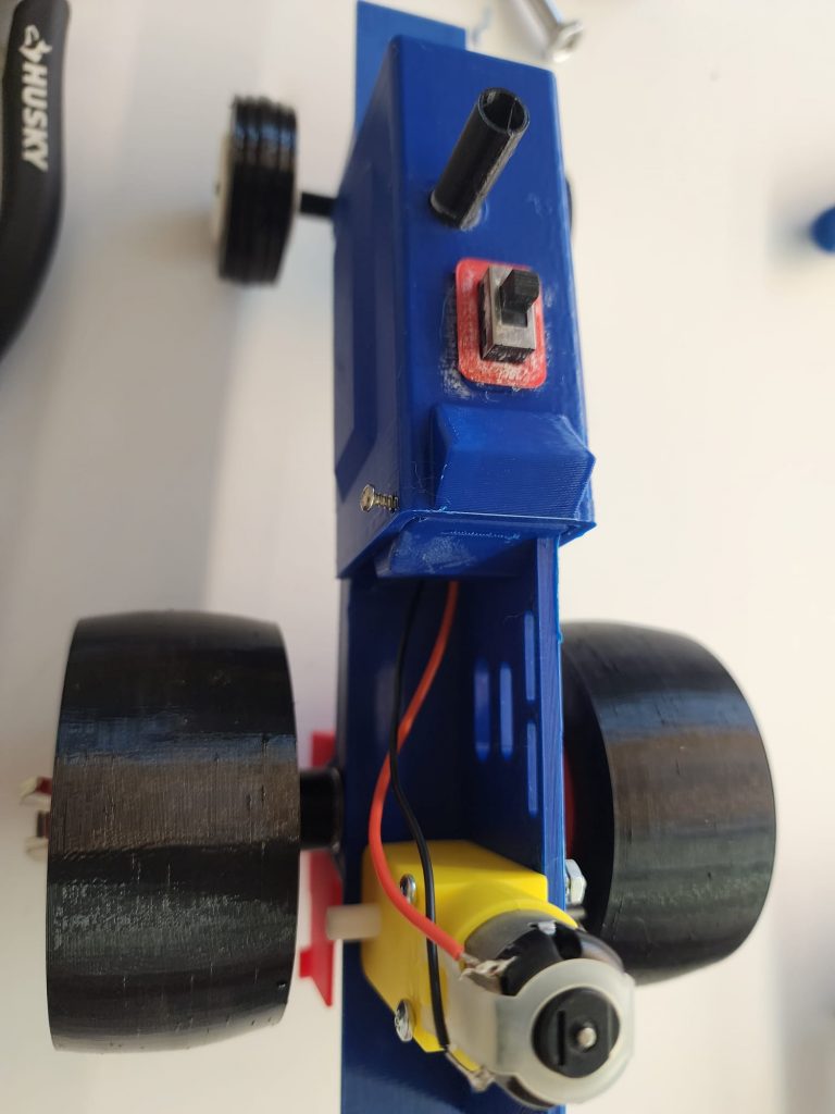
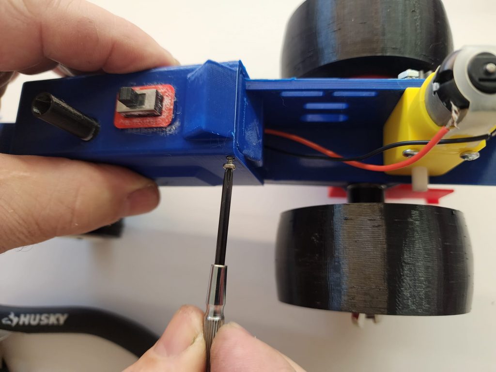
Feed the wires of the switch/switch housing assembly into the switch cut-out from the top. (see figure #12). Glue the switch housing in place. Connect the 2 wires from the switch to the top clamps of the terminal block. Install the body hinge screws from the hardware kit, they are 2-56 sheet metal screws. The holes in the body line up with the holes at the top of the dash. (see figure #13).
Step 12

Step 13
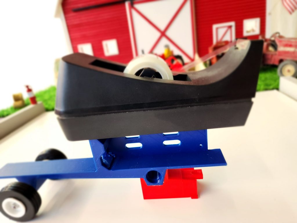
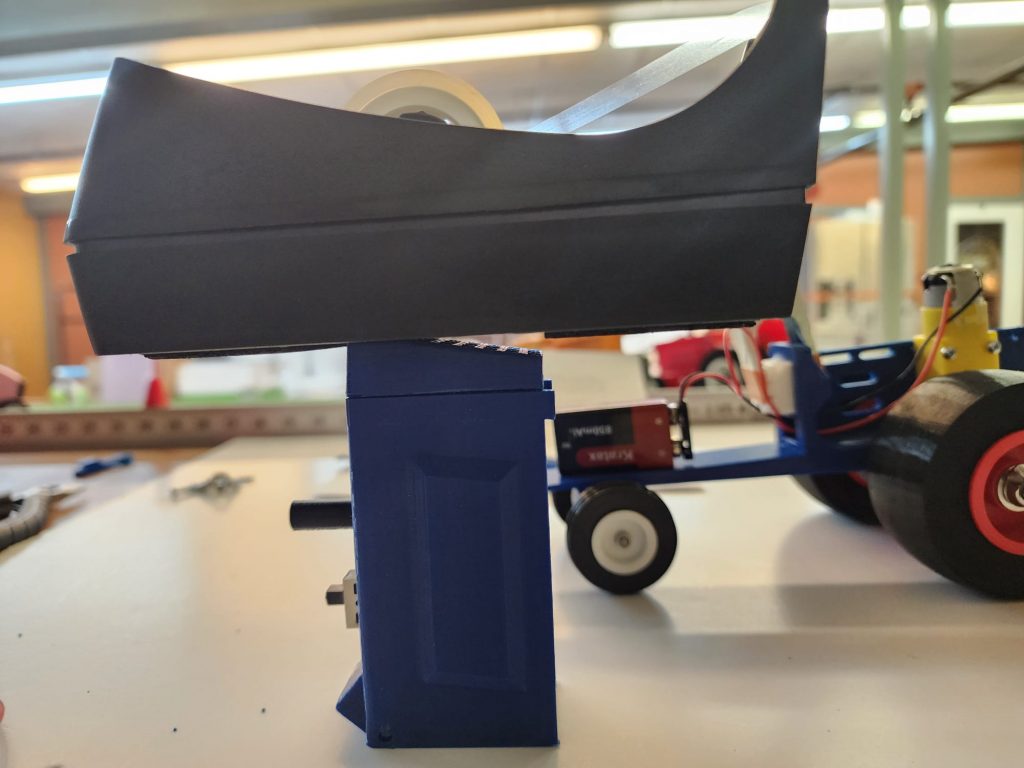
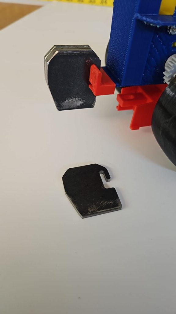
Slip the weight brackets, (#25 and #26) in place, front, and rear. The wider bracket generally is needed in the rear position. The kit comes with 10 suitcase style weights, found in the hardware kit. They slide onto the bracket from the side. (see figure #14).
Step 13
Step 14
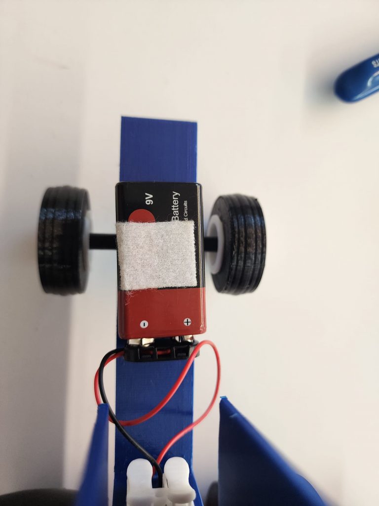
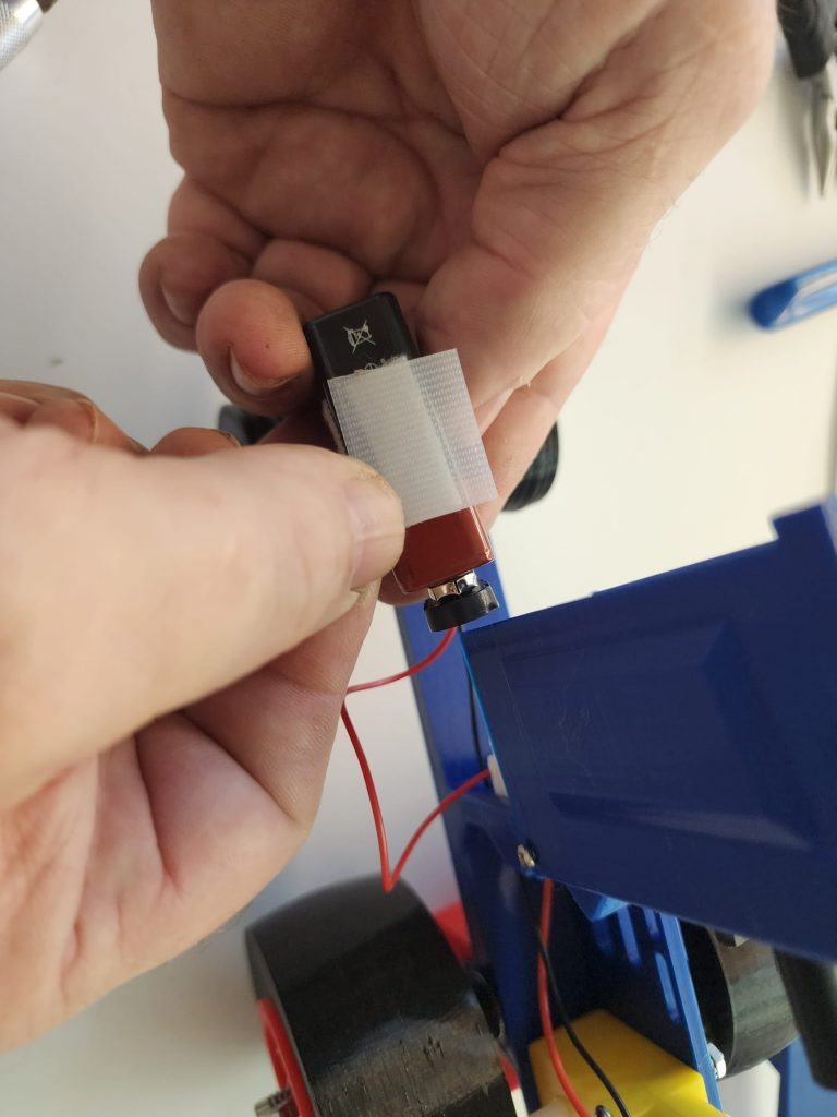
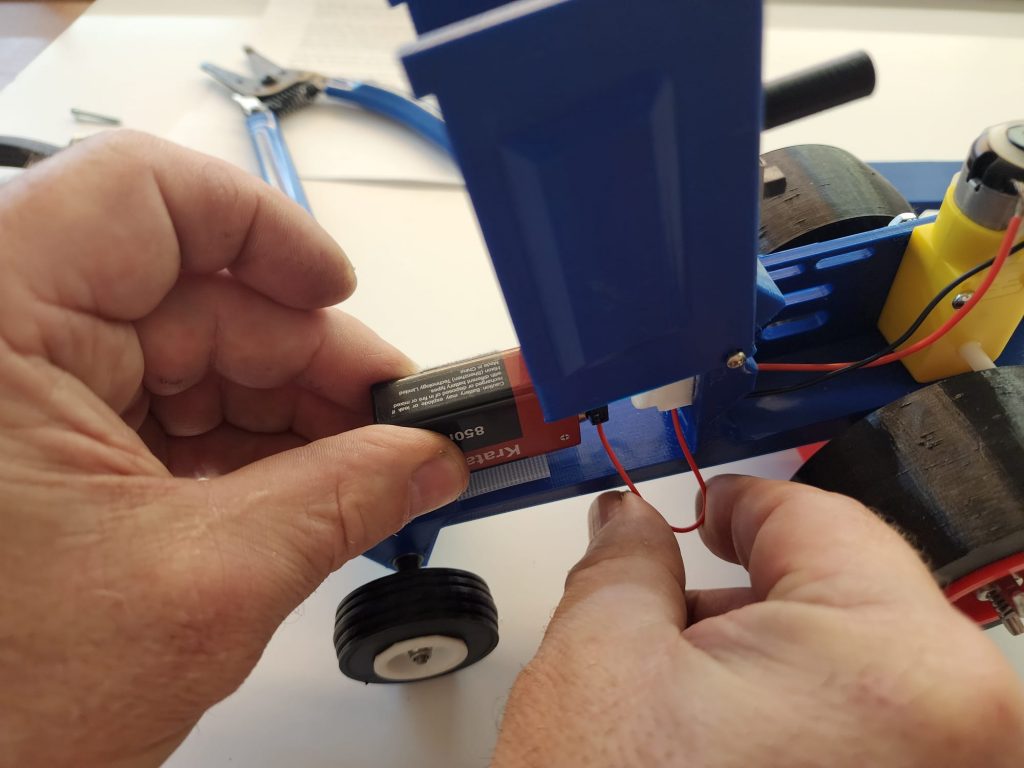
Apply the Velcro system to the battery and to the location/s of your choice on the tractor. One side of Velcro is the Hook side, (stiff), the other is the Loop side, (soft). Apply the hook side to the tractor and the loop side to the battery. (see figure #15).
Congratulations!
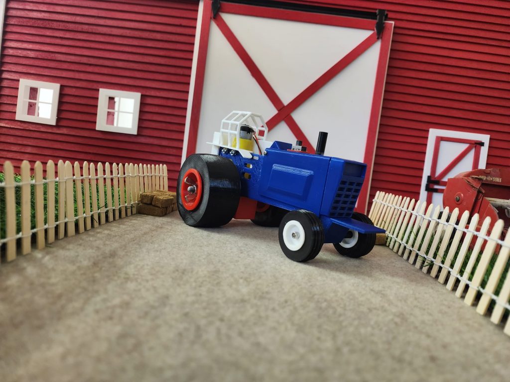
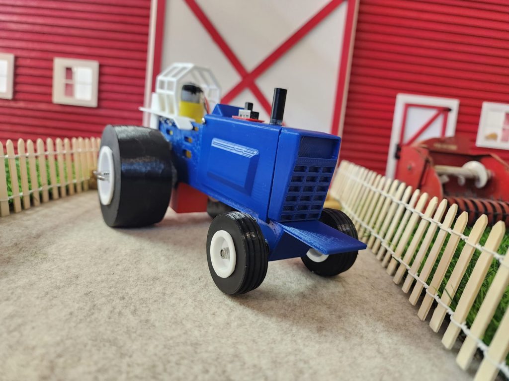
Your Mech Tech Models pulling tractor is complete. Feel free to apply paint and decals if you wish, these items are all available in our on-line catalog @ mechtechmodels.com.
OPERATION
There is a lot of physics involved with tractor pulling, whether it be full scale machines or the Mech Tech Model you just built. Learning how the tractor will respond under different conditions, and making the right adjustments is the key to success. Track surfaces vary and offer different traction values. These values may even change with humidity, dust, or other contaminates. Finally, they will change with use. You may or may not be in control of track conditions, so if you want to learn, the best thing to do is practice. If it is a sanctioned Mech Tech Models event, the track will be painted wood with brown matte or satin paint.
BALASTING
Determining where to place the movable weights on your tractor will be one of the decisions you make. Your tractor has 2 positions to place the suitcase style weights. Also, you may move the battery pack forward or backward. If the track surface seems slippery, more weight is needed over or behind the powered axle to give more traction. If the track is sticky and offers a lot of traction, more weight needs to be shifted forward to keep the front end of the tractor down. Ideally, the tractor will lift the front wheels off the track about a ½-1 inch near the end of the pull, thus placing all the weight on the rear tires and offering the most traction. Also, if the tires are slipping a little and the motor is not bogged down, you are getting all the torque to the track.
GEARING
The 90-degree gearmotor setup allows for easy gear change. The kit is supplied with two pinions, 15 tooth and 20 tooth, they attach to the output shaft of the gearmotor. There are 3 planetary gears, 32, 40, and 44. Typically when the tractor is lighter, or the track is slippery, you will want a faster gear. The opposite is true when you add more weight, or the track is sticky. Again, ideally at the end of the pull you want enough torque on the rear wheels to lift the front and slip the tires.
STEERING
During a sanctioned pull, you will be allowed to steer your tractor. One method is to use a transparent plastic scoop, or by tapping a pencil on one side or the other of the body. It is best to allow the tractor to wander from side to side naturally, only correcting it from going out-of-bounds. Over steering will shorten your distance.
Tires
All the tires supplied with Mech Tech Model tractors are the same theoretically. They are produced by 3D printing just like many other parts of the tractor. 3D printed parts will vary because of several variables in the printing process. Tires are printed in batches or sets and kept together so the two tires supplied with each tractor should be as similar as we can provide. Simply wipe them with clean water and dry them before each hook.
REPAIR AND MAINTENANCE
Hopefully, you will not experience any breakdowns. During the rugged testing we put these tractors through we never had any issues with any part. In the unlikely event something breaks, don’t worry! There is more where that came from. Visit mechtechmodels.com/parts. If you don’t see it on the list, well, that would be our fault, let us know and we will make it available.
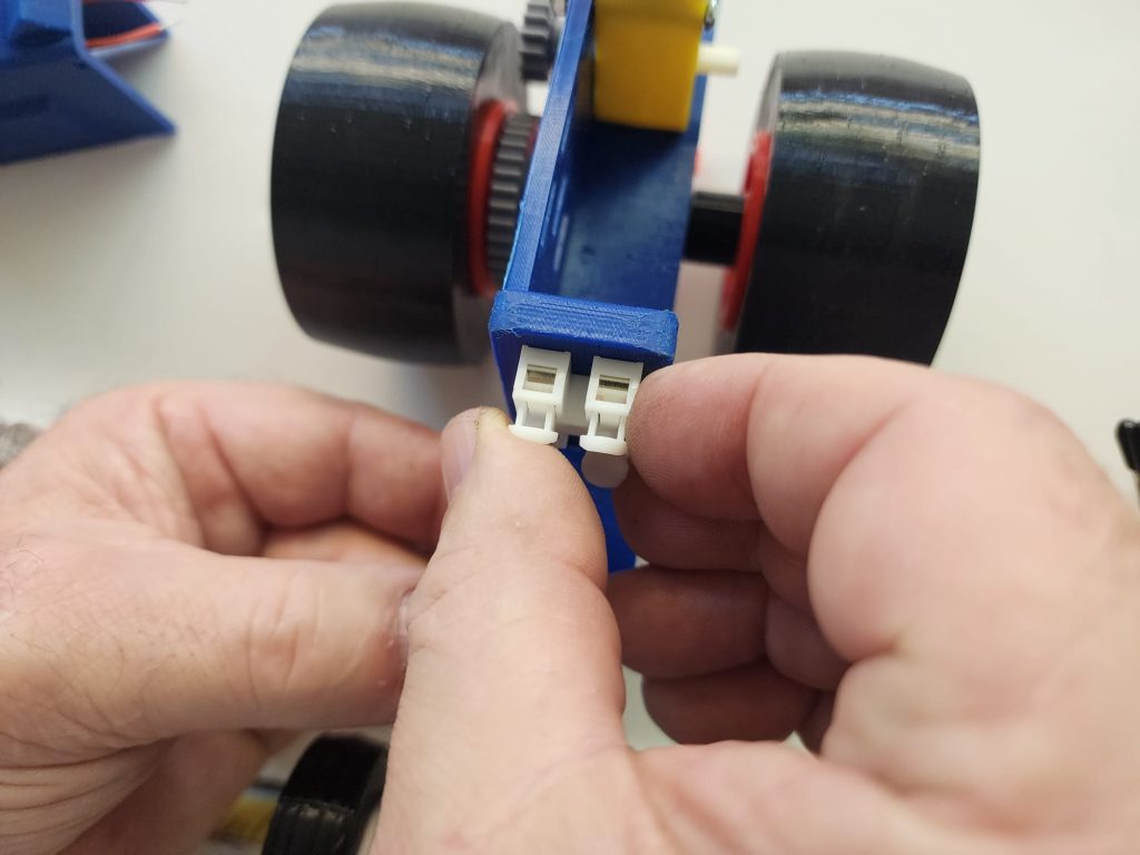
The tractors are maintenance free. However, if you would like, the motor is easily removed from the gear box by unhooking the white tabs and lifting the motor. A small amount of light oil can be dropped onto the gears. Replace the motor and re-hook the tabs. (see figure #1).
UPGRADES
Depending on the model frame you purchased, there may be upgrades for it. For example, the Stock frame has a place for one motor, but you can add a second battery pack for more power/speed. You would now have a Super Farm Class tractor.
The Twin Turbo frame has a place for two motors. You have the option to only run one motor, Stock Class, or two motors, Super Stock Class, or two motors/ two battery packs, Pro Stock Class.
The In-Line 20 MM frame and the In-Line 25 MM frame only have a place for 1 motor, but they can be upgraded with a second battery pack. 20 MM becomes Light Limited Super Stock, and the 25 MM becomes Light Limited Pro Stock.
MOST IMPORTANLY, HAVE FUN!
